Korg Monotron – LFO as one shot EG and gate to trigger LFO reset

Monotronhackagain

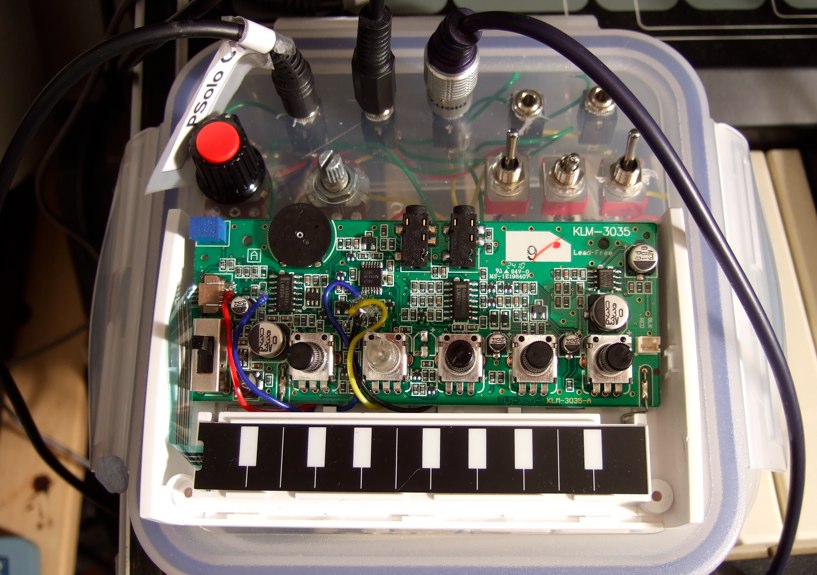
I’ve got quite far with the Monotron fiddling, mostly to try and stop the audible click that happens when the gate is turned off.

I’ve put switches on it to disconnect the ribbon keyboard and the gate input, so that the Monotron drones constantly, then doing Beatnic’s mod to turn the LFO into an EG, which means removing the 1k resistor at R33:

Monotroneg

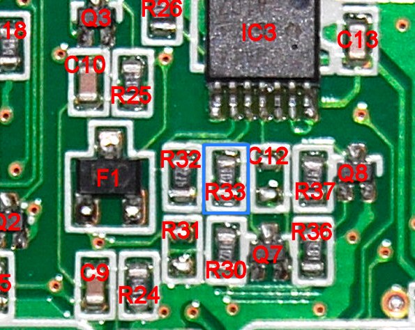
…and soldering a couple of wires to the pads of R33. Treat the wire to the top pad as B and the bottom pad as A, and have a look at Beatnic’s diagram – this is what you’ll need to recreate. I just used a small bit of stripboard, but I’m sure you could wire it point-to-point and keep it all in the Monotron case. I used a 0.0047uF cap for C1. (see update at bottom of post)

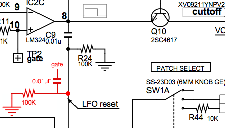
There might be a cleaner/better way of doing this, but when it’s set up for external CV/gate control, the rightmost switch is set up so that when it’s droning (external gate input off) the gate is passed through to the LFO reset point through a replication of C9/R24 to turn it into a trigger, otherwise the LFO won’t reset until the key is released (see LFO reset point on Korg Monotron for a demo). The simple gate-to-trigger mod is the red section added to the schematic:

Monotron_lfo_reset_diagram

Here’s a quick demo – the middle switch of the three is the LFO/EG switch, the right hand one is the gate input on/off switch.

At 1m10s I switch the gate input on and you can hear the click at the end of the note that I was trying to get rid of. It’s more obvious when the filter is tuned low. It’s still really hissy and the pitch knob is ferociously twitchy, but it sounds pretty good. It would be nice to build in some fine tune adjustment for the pitch somewhere.

Update – May 2014

Beatnic’s schematic is long since lost to his website change a while back – it’s my own fault for trying to link back to the source. As people still seem to be interested in how to do this mod, I’ve recreated the schematic from the stripboard in my fiddled-with Monotron. Here it is :

Monotron LFO as one-shot

The resistor I’ve labelled Rx essentially replaces and does the same job as R33 when switched in. The 4.7nF cap goes to ground, and the 100k resistor goes to Vdd, which I think is 5v. Let me know if this works in the comments…

Tagged under , , , , ,

24 comments

  1. 24th January 2011plasticanimal says:

    I’ve tried building it a couple of different ways and still can’t get the LFO to re-trigger from the ribbon keys. I’m assuming the replication of C9 and R24 is just for external gate in. I don’t understand why the LFO doesn’t respond to gate from the ribbon while in EG mode. Anyway, I’m to tired to keep at it tonight.

  2. 24th January 2011ua726 says:

    Yep, sorry – I should’ve made it clear about the recreation of C9/R24, I’ll edit that. The translation of Beatnic’s article wasn’t terribly clear about which pad was A and B on his diagram, I had to swap them about until I got it working. Just checked again and I’m pretty sure that the top pad on R33 is B – I’m connecting it to a 1k resistor and then to the middle point of a switch, with the bottom pad connected direct to one side of the switch, and the other side of the switch to the bit of stripboard with the recreation of Beatnic’s circuit. Tested it as working from the ribbon and external gate. Good luck with it, hope you get it working.

  3. 25th January 2011plasticanimal says:

    Yeah, that’s basically how I had it set up first. I was just using a different cap and tapping VCC in a bad spot I guess. Works perfect now. All I have to do is wire up the amp vactrol get some small switches and figure out how to cram it all in. Thanks for the help BTW,very encouraging.

  4. 28th January 2012Dan says:

    Your articles about monotron are realy helpfull.I have a couple questions 1- do you know what is the VBIAS labeled point ni the monotron? what does it control? also for the VCO labeled point, i hooked my sequencer there, but i could not figure it out what does it change.2- Please, can you upload a photo of the LFO EG mod made on your monotron? I read the schematics and everything, but i can’t figure it out how to do it 🙂 it would be easier if i see the stuff that you hooked up in the board.Thank you!

  5. 28th January 2012Dan says:

    Hey, i think that i’m getting how to do the LFO EG mod, but i don’t know where does the 100k resistor go in the beatnic’s schematic. what does that triangle means? i Know that the capacitor goes to ground. I checked this schematic also http://monotron.adornomedia.com/viewtopic.php?f=3&t=24&p=84&hilit=amp#p84 and that point that i don’t know where it is is labeled as VA.THank you!

  6. 29th January 2012ua726 says:

    @dan I think that VBIAS defines the virtual ground around which the waveforms swing around – I’d leave it alone if I were you. I think the point labelled VCO is the raw output from the VCO, but I can’t remember testing thisThe only photo I’ve got is the one above, here’s the version on flickr. http://www.flickr.com/photos/equaliser/5840184585/. If you zoom in, the blue and black wires attached to R33 are the ones. I could take a photo of the thicket of wires that sprout out of the back of the Monotron, but I don’t think it’ll help too much – hopefully you’ve got enough to go on from the post and the comments above.The triangle on beatnic’s schematic is +5v – there’s a point on the bottom marked Vcc which will do for that.

  7. 29th January 2012Dan says:

    Cool! many thanks for helping me!I have half done the modification, i got to make the A part of the schematic and it is done, i will do that later. So, I finally guess that the triangle in beatnic’s chematic is the point where you solder the yellow wire, right?You helped me a lot! thanks.And those red and blue cables wired on the left of the monotron, what do they do?

  8. 29th January 2012ua726 says:

    Dunno if you’re quite there. Just to explain a bit further – I removed R33. To the top pad of R33 I soldered a blue wire – on the other end of that wire is a 1k resistor, and the other end of that resistor to the middle leg on an SPDT switch (which has three "legs" on it).I soldered a black wire to the bottom of R33, and soldered the other end of that to one of the outside legs on that switch. The other leg I soldered inbetween the 100k resistor and a little orange disc ceramic cap, marked with 472. The other end of the 100k resistor goes to +5v, and the other end of the cap goes to ground. The yellow wire in my picture is from R24 – this is attached to a resistor and a capacitor to turn the gate (from my sequencer) into a really short trigger pulse, so that the LFO gets reset when you press the key down. If you don’t have this, the LFO only gets reset when you release the key.I can’t remember what the red and the blue wires were for, I think they’re so that I can switch between external gate and the ribbon.hth

  9. 29th January 2012ua726 says:

    btw it’s worth checking out my other posts on this if you haven’t, there’s a bit more explaining in them: http://www.ua726.co.uk/tag/monotron

  10. 1st February 2012Dan says:

    Hey, I made it! it was very hard because everything is so little and the board breaks very easy, but i made this mod and it works fine! I reccomend to everyone who make this mod to use HOT GLUE GUN when finishing the soldering, but use it only AFTER you check it works fine ( the soldering points in the board breaks a lot 🙁 …)

  11. 1st February 2012ua726 says:

    woohoo! nice one Dan.Agree about the hot glue gun thing, I dribbled some glue over the joints to keep them in place.

  12. 15th February 2012Noah says:

    How am i supposed to solder the leads to the pcb where the small resistor was? I tried on one, but the small solder pads broke off. Also, would there be any way to repair this? Thanks!

  13. 15th February 2012ua726 says:

    @Noah shit one. I dunno how to repair the pad. I’ve never done this, but suggest either scraping a bit of the solder resist off and soldering to the track, or alternatively work out what is connected to the pad and solder to that instead. Looking at the schematic, one side of R33 is connected to one of the legs of F1, and the other end is connected to one side of C12.hope you get it sorted.

  14. 18th February 2012Noah says:

    Okay, so I could take a 1k resistor and use that to connect c12 and f1 (just by touching the contact points). This would enable the lfo when the correct places are connected, right? And then once I know the spots I could solder my leads to them?

  15. 18th February 2012ua726 says:

    Yep, that sounds about right. Just doing a quick continuity test on what I can get to on my mine (most of it is now covered in glue) the bottom pad of R33 is connected to the left hand leg of F1.

  16. 22nd February 2012Noah says:

    Thank you so much! I was much more careful this time and also hot glued the connections down after making sure they were stable. The envelope is sounding great!

  17. 22nd February 2012ua726 says:

    nice one! glad you got that sorted.

  18. 4th March 2012Noah says:

    On a side note, did you ever come up with a way of reducing the clicks following every note, other than using an external envelope generator?

  19. 4th March 2012ua726 says:

    My way around the click was to let the Monotron drone, and use the LFO as an envelope on the VCF. plasticanimal in the comments for this post : http://www.ua726.co.uk/2011/01/05/korg-monotron-hacking/ was was looking at tying a vactrol to the output amp, I’ve not tried that approach myself.

  20. 7th March 2012Noah says:

    Okay. I’m really confused about the whole drone mode thing. I don’t quite understand how you added this feature. And if i wanted to add the LFO reset modification, would I be able to do that with Beatnic’s midi mod? You mentioned external cv and gate control so I wasn’t sure. Sorry for all these questions.

  21. 10th August 2012ua726 says:

    Really massively late on replying on the drone thing, sorry… I think I just disconnected the gate input/ribbon to start the Monotron droning, although it would probably be better to tie it to a positive voltage. Dunno about Beatnic’s midi mod, I would imagine it would be ok tho.

  22. 15th May 2014Léo says:

    Hey, it’s me again from the comment on the youtube video.

    I used this other method for turning the LFO into an EG : http://houshu.at.webry.info/201006/article_3.html
    I think it’s more safe as you don’t have to solder directly onto one of those tiny SMT resistors, and I guess it doesn’t change anything from your mod.

    I’ll buy a double switch tomorrow to test your first scheme, that will at the same time conduct the gate signal into this point rather than the gate point on the PCB, and connect the Vcc point to the gate point to keep the monotron playing, if I understood correctly ?

  23. 15th May 2014ua726 says:

    Hey Leo

    Now you mention it I remember that it was difficult soldering to the SMT resistors, so you’ve probably chosen the best method for turning the LFO in an EG.

    The gate to LFO reset/Vcc to gate point double switch sounds like it should work.

  24. 18th May 2014Léo says:

    Okay, I just did it !
    It’s brilliant, I played sequences from my 303 that feel much more natural than with the click coming again everytime. It’s a shame your mod is not as popular as some other ones…

    I added the square wave (I like it better than the saw), with an op-amp doing a comparator with the saw, the square is coming at a higher level than the saw (0-5V), so by adding a simple tension dividing bridge with a pot, you can completely overdrive the filter when you want it, and it gets real angry. It gets so loud than you cannot make the filter self oscillate and the noise seems much more lower, I love it.

Write a comment: