Sketchy Arduino dual frequency counter

Frequency counter board and display

After much fiddling around trying to build a Roland System 100 VCO – over a period of actual months – I thought it would be handy to have a frequency counter to tune the thing in. And then I thought I could make it a dual one so I could tune my Model 101 keyboard exactly as well, being as it doesn’t have an octave selector, just a coarse frequency knob that sweeps from less than 10Hz to over 10KHz.

And then, I thought I could add some sort of indication of the pulse width of the signal, because I like tuning the oscillators as close to pure squares as possible to get that Roland-y low square sound.

Here’s a mercifully short video, with the prototype DIY System 100 VCO providing the constant drone against a real wiggling Roland VCO.

The System 100 outputs a 0-10v (ish) square wave, so we go in through a voltage divider, then to one side of an LM358 set up as a unity gain buffer, and then on to a LM319 dual comparator, configured with a bit of hysteresis as described at ermicroblog.

From here the signals go to pin 2 or 3 on the Arduino, and every time the pins change state an interrupt happens, and the time is noted. The LM319 is probably total overkill, but I wanted to make sure I was getting clean square waves and it was all I had in my bits box.

This is the sketchy bit – because you can’t interrupt an interrupt (at least on the Arduino), there’s potential for interrupts to get missed, so the code chucks out any readings that look ridiculously long or short. The result displayed is a median of a number of readings.

I did think about using external counters so as to avoid missing any ticks, possibly using a pair of Attiny MCUs talking to the Atmega328, but I found that just chucking out any rubbish results was good enough.

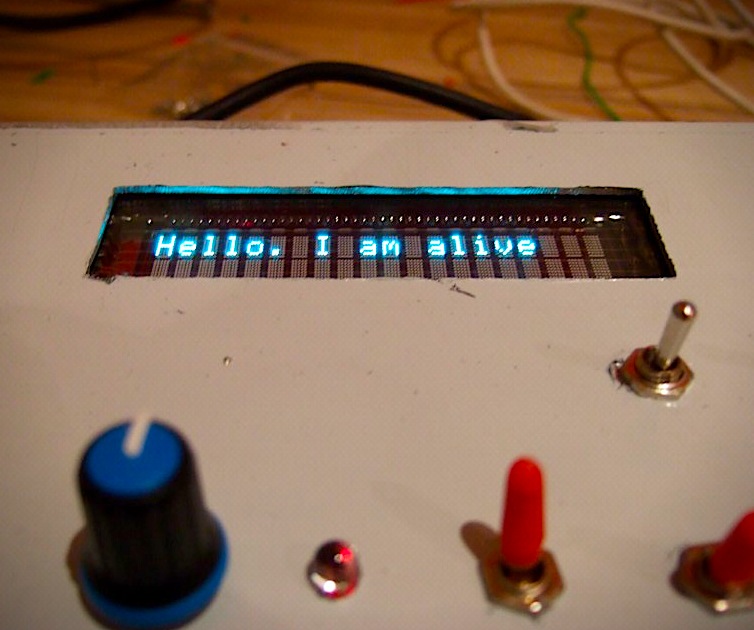
I’m only really interested in the audio range, so below about 8Hz it gets a bit sketchy with the display falsely wrapping around to >15KHz, but goes up to about 40KHz. In the video you can see the update rate really slow down as the pitch gets lower, because it takes longer to gather the samples to take an average.

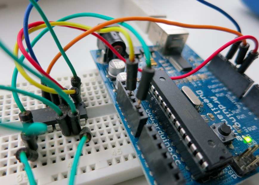
I’m chuffed that my first attempt at transplanting the Atmega328 chip from an Arduino board onto a stripboard has worked out. I borrowed Nathan Chantrell’s Veroduino layout, and moved the electrolytic capacitor out the way so there was space for the regulator to lie flat. The regulator really needs a heat sink, it’s too hot to touch with the Samsung VFD running from the same supply.

It’s probably overkill to use the 328 given the unused I/O, but it would’ve been more of a faff to try and find something smaller just to save a bit of board space.

Here’s a Gist with the code, and this is the jumper-happy layout.

Arduino frequency counter stripboard layout

Idiot things I did wrong included using a shit switching power supply that caused the frequency readout to jump around; a heavyweight linear supply sorted that out. Also with the thought of matching the frequency to a musical note, I created an array full of strings and filled the RAM, which caused the Arduino to crash randomly.

Next is the bit I always struggle with, putting it in some sort of box – thinking of a Ponoko/Razorlab acrylic case.

No Comments

Testing the MCP4922 with an Arduino

Arduinomcp4922

On the ever busy Muffwiggler synth forum, someone asked about some test Arduino code for the Microchip MCP4922 SPI DAC.

This program outputs ever rising voltages on each of the DAC channels, until they get to the maximum level of ~5v, when it loops back to 0v again. It also prints the number sent to the DAC to the serial monitor, so you can check what it’s doing.

Like it says, it’s mostly borrowed from MrBook’s blog post on controlling a Gakken SX-150 through MIDI.

/*
MCP4922 test
most code borrowed from
http://mrbook.org/blog/2008/11/22/controlling-a-gakken-sx-150-synth-with-arduino/

connections
====================================================

+5v           > 4922 pin 1
Ard pin 10    > 4922 pin 3   (SS - slave select)
Ard pin 13    > 4922 pin 4   (SCK - clock)
Ard pin 11    > 4922 pin 5   (MOSI - data out)
Ground        > 4922 pin 8   (LDAC)
+5v           > 4922 pin 11  (voltage ref DAC B)
Ground        > 4922 pin 12
+5v           > 4922 pin 13  (voltage ref DAC A)

4922 pin 14 DAC A > 1k resistor > synth CV in

*/

// MCP4922 DAC out
#define DATAOUT 11//MOSI
#define DATAIN 12//MISO - not used, but part of builtin SPI
#define SPICLOCK  13//sck
#define SLAVESELECT0 10//ss

int i = 0;

void setup() {
  SPI_setup();
  Serial.begin(9600);
}

void loop() {
 i++;
 Serial.println(i);
 write_note(i);
 if(i>=4096) {
  i=0; 
 }
}

void write_note(int i) {
  write_valueY(i);
  write_valueX(i);
}

// **************************************************
// SPI for DAC

void SPI_setup(){
  byte clr;
  pinMode(DATAOUT, OUTPUT);
  pinMode(SPICLOCK,OUTPUT);
  pinMode(SLAVESELECT0,OUTPUT);
  digitalWrite(SLAVESELECT0,HIGH); //disable device

  SPCR = (1<<SPE)|(1<<MSTR) | (0<<SPR1) | (0<<SPR0);
  clr=SPSR;
  clr=SPDR;
  delay(10);
}

// write out through DAC A
void write_valueX(int sample)
{
  // splits int sample in to two bytes
  byte dacSPI0 = 0;
  byte dacSPI1 = 0;
  dacSPI0 = (sample >> 8) & 0x00FF; //byte0 = takes bit 15 - 12
  dacSPI0 |= (1 << 7);	  // A/B: DACa or DACb - Forces 7th bit  of    x to be 1. all other bits left alone.
  dacSPI0 |= 0x10;
  dacSPI1 = sample & 0x00FF; //byte1 = takes bit 11 - 0
  dacSPI0 |= (1<<5);  // set gain of 1
  digitalWrite(SLAVESELECT0,LOW);
  SPDR = dacSPI0;			  // Start the transmission
  while (!(SPSR & (1<<SPIF)))     // Wait the end of the transmission
  {
  };

  SPDR = dacSPI1;
  while (!(SPSR & (1<<SPIF)))     // Wait the end of the transmission
  {
  };
  digitalWrite(SLAVESELECT0,HIGH);
}

// write out through DAC B
void write_valueY(int sample)
{
  // splits int sample in to two bytes
  byte dacSPI0 = 0;
  byte dacSPI1 = 0;
  dacSPI0 = (sample >> 8) & 0x00FF; //byte0 = takes bit 15 - 12
  dacSPI0 |= 0x10;
  
  dacSPI1 = sample & 0x00FF; //byte1 = takes bit 11 - 0
  dacSPI0 |= (1<<5);  // set gain of 1
  
  digitalWrite(SLAVESELECT0,LOW);
  SPDR = dacSPI0;			  // Start the transmission
  while (!(SPSR & (1<<SPIF)))     // Wait the end of the transmission
  {
  };


  SPDR = dacSPI1;
  while (!(SPSR & (1<<SPIF)))     // Wait the end of the transmission
  {
  };
  digitalWrite(SLAVESELECT0,HIGH);
}

One thing I’d point out that I’ve not seen much elsewhere is that by default the MCP4922 seems to be set to output with a gain of 2. So as we’ve got it setup, rather than the number 4095 representing the maximum voltage that can be output, 2047 will actually make us hit ~5v . Setting the output gain select bit on output will change the gain from 2x to 1x.

dacSPI0 |= (1<<5);  // set gain of 1
No Comments

Hello, I am alive

Iamalive
No Comments