Voltage controlling the CGS30/SH-5 bandpass filter

I’ve been having another go at voltage controlling the cutoff of a SH-5/CGS30 bandpass filter. This is my previous attempt, based on attenuating and offsetting the input control voltage to a reasonable range for the LED to light over:

This time I started out with a pair of 2SK30A-GR FETs, but the swept range was small and the sound became oddly distorted as the cutoff was pushed lower.

I gave up and went back to the homemade vactrol, this time with a diffused red LED. I rebuilt the circuit to offset and attenuate the CV signal, again based on Ken Stone’s joystick controller. I’ve managed to get a reasonable sort of range with this set-up, although the resistance range could be wider, and the response wasn’t particularly linear.

I was doing some testing, and just wanted to check the response against a known quantity. Here’s the Doepfer A-120 LPF fixed to self-oscillate at full resonance swept with the triangle from my MFB Dual LFO, peak frequencies graphed log-wise in Sonic Visualiser.

A-120 filter swept with MFB LFO tri wave

Which doesn’t quite look right, all wobbly when it should be a triangle with straight edges. Suspecting the filter, I connected the MFB LFO to one of my oscillators and got a similar result.

Trying a different modulation source, here’s the A-120 swept with the LFO in my MS20:

A-120 filter swept with the MS20 LFO

Which looks much better, proving that this particular MFB LFO is even wonkier than my teeth. The triangle is leaning slightly forwards, presumably because the MS20’s LFO shape control wasn’t quite centred.

Going back to the CGS30 bandpass, because it won’t self-oscillate here it is being fed with a one note looped pattern, set to high resonance and with the filter frequency swept with the MS20 LFO.

CGS30 DIY BPF swept with MS20 LFO - log display

The stepping is presumably the filter picking out the harmonics in the square wave.

Flipping from a log display to a linear display, we get…

CGS30 BPF swept with MS20 LFO - lin display

Which is pretty close to the MS20 LFO waveform. Maybe an anti-log LED driver might fix this.

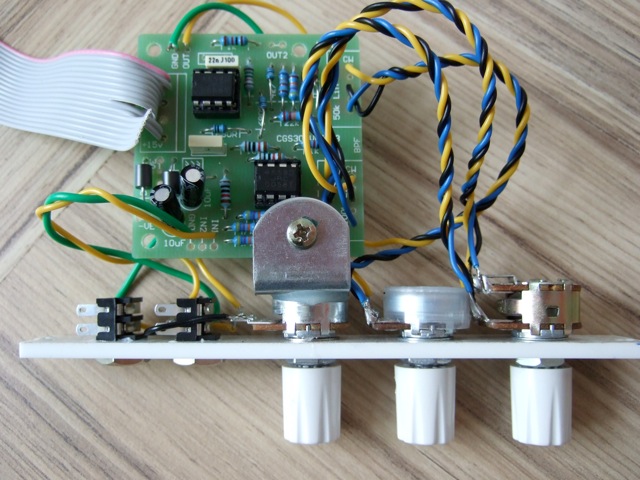
Masatoshi Katsube has been here before. From his linear LED brightness driver circuit, I got this:

anti-log LED driver circuit

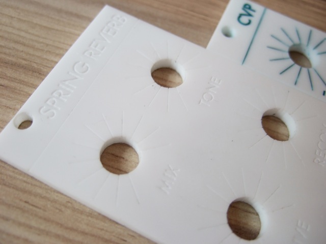
Imagine a couple of LDRs pressed up against the red LED in the right hand corner, with the wires of the two LDRs going to the places where the dual pot would be on the CGS30 circuit diagram.

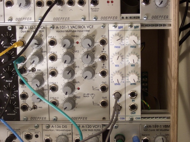
I’m running off 14v because I’m running this circuit from the same PSU as the recreated System 100 innards on my desk. The 500K pot is for setting the offset of the input control voltage above 0V, which would be replaced by a fixed resistor in the final thing. Also the MS20 LFO is +/-2.5v, when modular LFOs tend to be +/-5v, so the voltage divider at the front of the positive op-amp input might need to change.

Inbetween the last measurements and the next time, the LFO shape got skewed even further, so I re-adjusted it to be as centred as I could. So we know where we are, here’s the DIY BPF swept by the MS20 LFO from the original circuit again:

CGS30 BPF swept by MS20 LFO (set to a centred triangle) - log display

And here’s the BPF driven from Masatoshi Katsube’s antilog circuit:

CGS30 BPF swept by MS20 LFO driven by antilog LED driver (triangle centred) - log display

…which is pretty good. It starts to flatten out a little bit as the frequency reaches the top of its range at about 4.2KHz, but it’s not bad. The lowest it gets is about 90hz, but it should get better when the LED and LDRs are encased in some kind of black hole. This is what it sounds like with the resonance cranked up.

I wanted to see how the frequency range compared to the original SH-5, so I recorded sweeping the filter over noise by wobbly hand.

Sweeping the SH-5 BPF by hand

The SH-5 gets down to about 60hz and just over 10KHz at the top, so we’re not quite able to control over the full range with this set up. I’m using 5539 LDRs which are specified as having a resistance of 30K – 90K at 10 Lux, it might be better with 5537s which have a resistance of 16K – 50K at the same light level.

Some further fiddling is needed but this seems like a viable method for voltage controlling the SH-5 bandpass.

No Comments

CGS30 BPFs built up with acrylic panels

Here’s some pictures of my silly band pass filters. Nice crockery, etc.

Image

The panel is laser cut from 3mm white acrylic by Razorlab through Ponoko, and they came out really well. They were ordered late on a Tuesday night – the confirmation email said that it would take up to 28 days (boooo) – but they were made up and dispatched by Wednesday lunchtime, and arrived on Thursday morning (hooray!).

I designed them in a bit of a hurry to try and get in on one of their offers, so I missed out the plus and the minus on the resonance pot, and for some reason the level pot is a bit further away from the resonance pot than it should be, but these are all my mistakes. I used the Pro-Modular templates for the panel outlines, and this incredibly useful scale generator for the lines around the pots.It worked out at about £27 (including a 20% discount) for 3 x 8HP panels and 4 x 4HP panels, so the 4HP panel above cost about £2.70. If I’d been a bit cleverer about organising the panels on the sheet to minimise the amount of cutting it should have worked out a bit cheaper.

0image

The legends are also laser engraved, and I used some of my wife’s old acrylic paints from the shed to infill the text, with isopropyl alcohol for cleaning off the excess. No complaints about the quality of the engraving from Razorlab, it all looks super sharp.

On the Polivoks filter I built a while back I lost all patience with the shitting thing and just decided to stuff a load of Blutack on it to fix the board to the front panel, but I made a bit more of an effort this time.

1image

Well, I used Araldite instead of Blutack, at least. I’d read around a bit now, and everyone says you really need to use (more expensive) 9mm pots for 4HP panels so you have enough room to attach the pots directly to the PCB. But I didn’t know that, so I stumbled along with 16mm Alpha-ish pots anyway, and it’s worked out… acceptably.

It does need two brackets really, ‘cos it’s a touch wobbly. Before I realised there was no room for pots threaded through a bracket, I tried to fashion one out of an aluminium L-channel using a random deadly looking power tool and was lucky to come away with all fingers attached.

I’m using some hard-to-find 100kC dual reverse log pots to try and get closer to the original response, which specified the same. This might sound ridiculously anal – alright, even more so – but with linear pots on my stripboard versions of this circuit I was finding that most of the action was crammed into the final travel of the pot. I say they’re hard to find but there’s someone in China selling them in batches of 3 on eBay.

I messed up on one of the boards, putting 100nF capacitors in instead of the specified 22nF, and it made it sound generally shitter: lowering the frequency range and made it less sharp. Which makes me wonder if those capacitors were a bit less than 22nF (15? 18?) what that might do to the sound. I’d recommend if you’re going to build these you will want to knock the 4.7k resistor on the other side of the resonance pot down to 470R or something. I used 680R on mine, wish I’d taken it a touch lower.

2image

Next time I’d make the screw holes more of a slot so I could close up the gaps, but apart from that I’m pretty happy with them. Sweeping the frequency of the two filters by hand sounds great, but I’d still like fix them up with CV control. It’s nice to get something built up with an actual front panel for a change.

1 Comment

CGS30 bandpass filter vs. Roland SH-5

Bandpassnightmare

A while back, like an idiot, I stripboarded six Cat Girl Synth bandpass filters, and wired them to a stripboarded DC mixer. The resulting nightmare mess is pictured above. It’s like I don’t believe in front panels.

At the time I’d lost my 15v power supply so I couldn’t give a test on the full wotsit. Well, I’ve found it now, so here’s the Roland SH-5, scratchy pots and all. Scuse the hiss.

And here’s the CGS30 BPF, running at 15v.

Near enough, really.

No Comments