Controlling the frequency on a CGS30 bandpass filter with a homemade vactrol

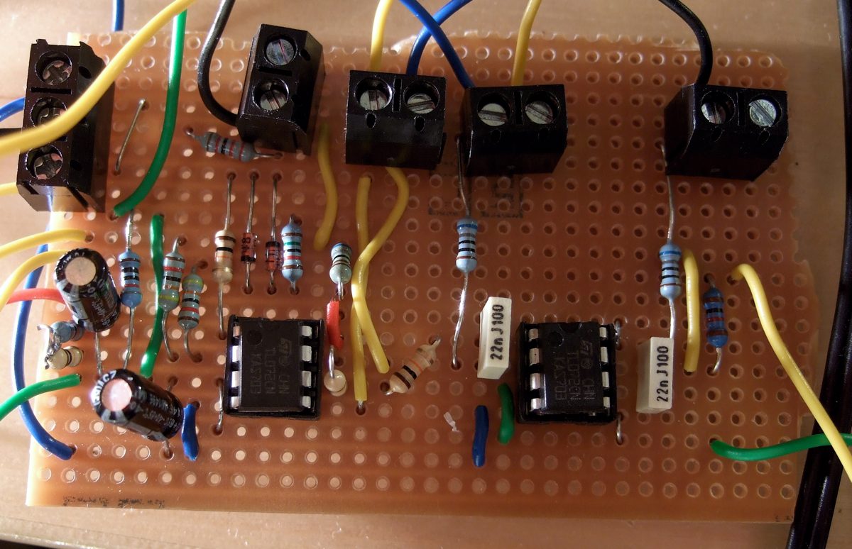
I’ve built five of my stripboarded CGS30 bandpass filters for a filter bank I’m planning. They all sound the same, or at least very similar, which isn’t much of a surprise. In my previous post I was wondered if using a 1458 opamp rather than a TL072 would get me closer to the SH-5 sound, and when I experimented I found that it made… no difference. Bah. Maybe a 15v supply will get me closer.
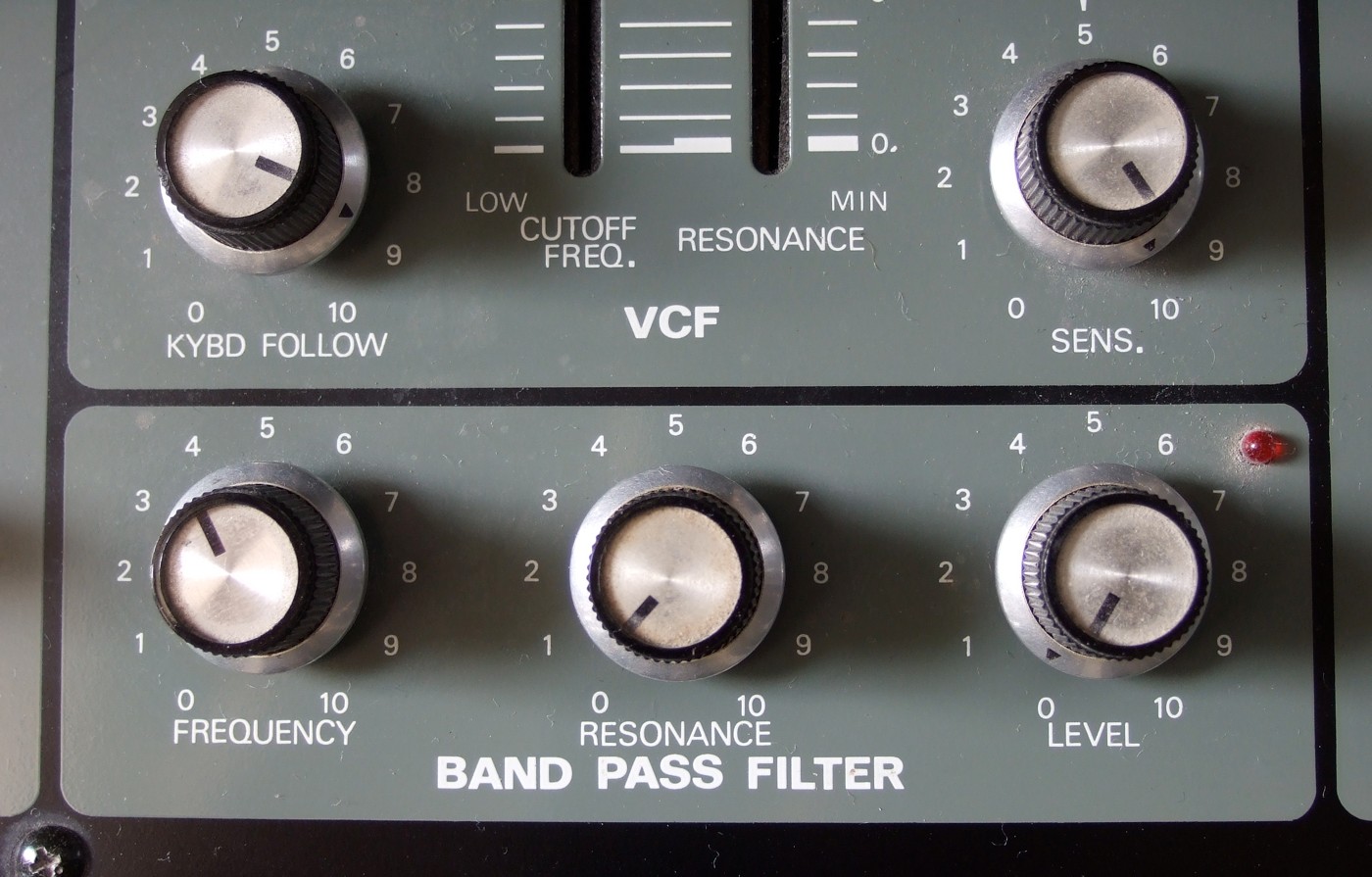
There’s no CV input as designed on the original SH-5 bandpass filter or Ken Stone’s version, so I’m been testing out using a vactrol (or rather a homemade LDR/LED combination) to convert the voltage from a triangle wave from an MFB Dual LFO into a resistance. I’m using a superbright green LED in front of a pair of 5539 light dependent resistors, which are just strapped across both of the pins on the frequency dual pot. Here it is in the open air – when it’s done it’ll best be put in a dark container.
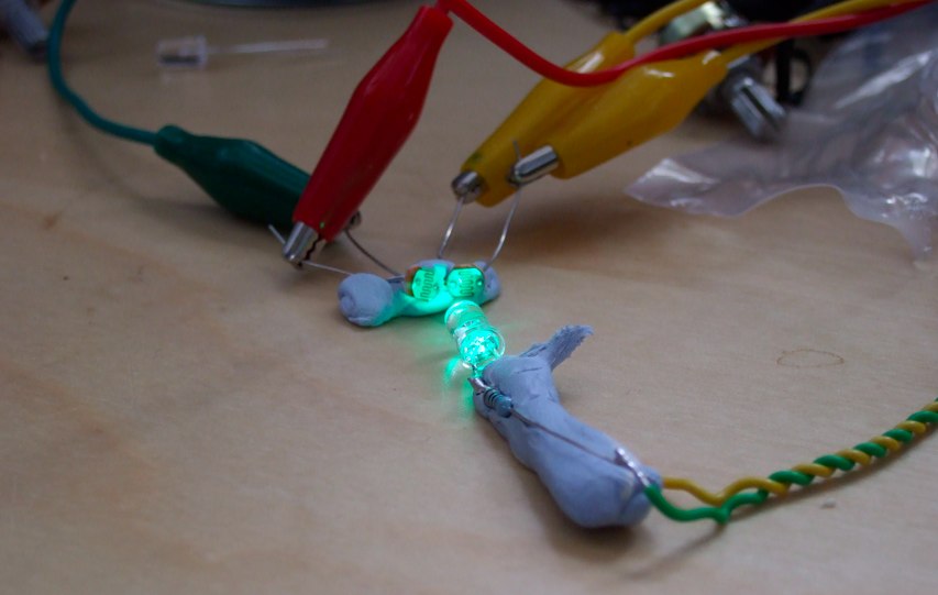
The output from the LFO is +/-5v, which is a problem because the LED won’t register anything below 0v, so we need to offset the LFO waveshape above 0v, which I’m doing using a breadboarded version of Ken Stone’s joystick controller.
So here’s an underwhelming demo of a sequence from my ridiculous, still unfinished (and now out of tune) Arduino sequencer, running two bandpass filters in parallel; one is static and the other is CV controlled – as the LED glows brighter the filter frequency goes up.
I’ve noticed (as other posters on electro-music and muff’s have found) that the response of the LED is non-linear – it gets up to a level of brightness quite quickly, and from then gets slowly more and more intense, which essentially means that the filter frequency suddenly jumps up from a low point and then slowly gets higher and higher. I’ve found that heavily offsetting and attenuating the voltage from the LFO has helped in trying to find the best part of the LED response curve, but it’s still not the best. It might be that a superbright green LED isn’t the best type to use. I chose green LEDS because the 5539 LDRs I’m using are most sensitive in that area of the spectrum.
Even though it hasn’t quite worked out as well as I’d hoped, I still think it’s worth adding CV inputs to the bandpass filter, some experimentation might improve it further.
