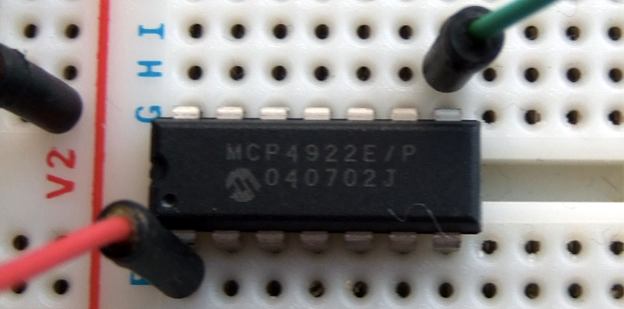
I’ve been fiddling with a Microchip MCP4922 12-bit SPI dual DAC for a while now for controlling my creaky old MS20 from an Arduino Mega, and it seems to work acceptably enough for my purposes, tracking a couple of octaves to +/-2 cents. It’s as cheap as chips – £1.77 from Mouser.
Originally I followed along with Mr. Book’s post on Controlling a Gakken SX-150 synth with Arduino – only he used an MCP4921, the single version of the 4922. His code (.pde file here) works well, only be sure to change the defined pinouts in the code if you’re using a Arduino Mega.
To save myself having to look up and cross reference the datasheet with the Arduino docs every time I use one of these, I’ve written up this table detailing what goes where.
Connection
MCP4922 pin
Description
+5v
1
Vdd
2
(not used)
Arduino Mega pin 53 / Arduino pin 10
3
CS – SS – slave select
Arduino Mega pin 52 / Arduino pin 13
4
SCK – clock
Arduino Mega pin 51 / Arduino pin 11
5
SDI – MOSI – data out
6
(not used)
7
(not used)
Ground
8
LDAC
9
SHDN
Synth control voltage in
10
DAC B Out
+5v
11
VRef B
Ground
12
Ground reference
+5v
13
VRef A
Synth control voltage in
14
DAC A out
Taking a look at the block diagram, it seems there are op amps buffering the output of the DACs. I’m taking the control voltage from the output of the MCP4922 through a 1k resistor and then into the MS20, and it seems to work well – here’s a demo on YouTube.
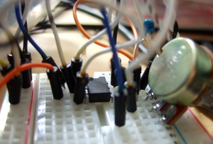
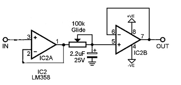
I’ve wanted to include a simple slide in my silly CSQ-100-style sequencer, and I’ve just got this circuit from a post at electro-music working, using a (probably not ideal) LM358 as a buffer running off a single +12v supply, and using a 1M pot rather than the 100k.
Here’s how it sounds on an MS20, with varying amounts of drunken slide.
The 1M pot is too big, I need to change the range to about 200k or so. From what I’ve read, I’d be better off with a log pot but I’ve only got linear ones to hand. I’m thinking I’ll switch the slide in and out of the circuit from the sequencer using a 4066 switch, that’s the next step.
Update: Here’s the MS20 being triggered by the sequencer, using a 4066 to bring the slide capacitor into circuit on 5v triggers from the sequencer, so the portamento only happens on certain notes. Initially I was trying to power the 4066 off +12v and switch it from +5v – If I’d have read the datasheet I would have realised it needs Vdd to switch, duh. Got there in the end.
I’ve been fiddling with dividing a Sync24 signal for a while now, and this is the messy result.
…lots of flashing lights. Sync24 – more commonly known as DIN sync, after the connector used – is a pre-MIDI standard for synchronising drum machines and sequencers. It works at 24 pulses per quarter note, so for each bar you get 96 pulses, which the spec says should be at +2.51 volts.
The idea behind this mess of wires is to divide down the Sync24 signal – in my case from a x0xb0x or a TR-606 – and send that to arpeggiators and sequencers which step every time a pulse is received.
For example, to get a sixteenth-note pattern running off the Sync24 signal, I’d divide it by 6, but by using different dividers I could get all kinds of different rhythms.
Previously I’d tried to be all clever-like and do it with logic chips, using 4017 decade counters to do the same thing, but it didn’t quite work. The divided signal was subtlely, maddeningly out of time with the source signal. It seemed to be only a matter of a pulse or two, but it was definitely audible.
With a big sadface on, I resorted to using an Arduino instead, and over-engineered the shit out of it, because it’s fun. Here’s a demo of the work-in-progress box, triggering an MS20, a Doepfer modular, and an SH-101 sequence.
Admittedly this is a lot of shenanigans for a thump-hiss rhythm like you’d get out of a 50p car boot 70s organ rhythm box, but I hadn’t really intended it as a drum sequencer.
So to explain what’s going here, the sync signal is coming in from my x0xb0x, and we dividing it up in different ratios and sending it out to four outputs. When it’s not in edit mode, the current tempo is calculated and displayed every crotchet. Clicking on the top row of four buttons puts it into edit mode for that output. All the red LEDs indicate edit mode for that output, all the yellow LEDs indicate a trigger output, and the green LEDs show which edit mode it’s currently in (divider, offset, swing, autoreset, polarity, random trigger).
Each output can be set to run at its own divider rate, from 1:1 with the clock (96 pulses per bar) up to one pulse every four bars. The start point for each divider can be offset, in sixteenths – so like in the video, you can get a snare on the 2 and 4, for example.
Each trigger can be either positive (in the demo used for the SH-101 and Doepfer percussion) or shorted to ground (the Korg MS20 uses these).
The SH-101 sequence in the video shows me flipping into random trigger mode, which works by playing a note depending on a random number being under a certain threshold. I’m not sure how musically useful this feature is at this stage – it could be better as a way to vary accents.
You can see me muting trigger outputs by holding down the shift key on the bottom right and clicking a track edit button. I’ve left a gap in the edit mode for swing – I’m not sure if I’ll get to this, I’m going to check out the swing on my 707 to see how it does it.
Not demo’d in the video, but I’ve taken some inspiration from the 4ms rotating clock divider and added an autoreset feature – each output can be set to automatically reset after so many clock pulses. I’m planning that this reset could also be triggered from an external clock pulse, I’ve a few analogue pins left over. I’m also wondering about whether to add a rotate input, and an AND/OR output, which could either AND or OR the signals from the four outputs together to one, really quite rhythmically odd output.I’ve had it running off my TR-606, which has a range of about 35bpm to about 235bpm, and once it got to much above 200bpm I noticed that it wasn’t keeping up. Not that I write much gabba, but I fixed it by running the (Sparkfun 7 Segment) display at 57600bps rather than the stock 9600bps. Took a while to work this out, ‘cos Adafruit’s own documentation is wrong, but here’s the necessary lines of code, I’m using NewSoftSerial as the interface, so assume that I’ve new’d up the mySerialPort earlier
mySerialPort.begin(9600);

mySerialPort.print("v");

mySerialPort.print(B01111111,BYTE); ?? // 127 in decimal

mySerialPort.print(B00000110,BYTE);?? // 6 in decimal