Roland System 100 VCF archaeology
I bought a Roland System 100 101 keyboard years back, so I’ve been after a 102 expander since, with no luck. The last one I looked at on eBay went for over £1500 – it’s nice, but that seems a bit ridiculous. Although look at the panel, it’s bloody lovely, in the style of some austere-looking 70s science equipment.
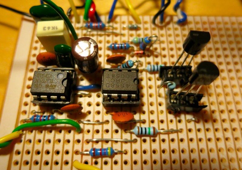
So a while back I spent the evenings of a couple of weeks obsessively working on stripboarding the Roland System 100 filter.
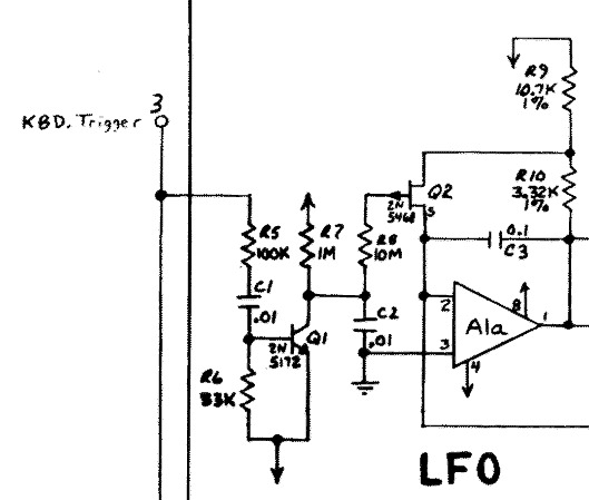
This is a bit of the schematic, I’ve been staring at it a lot.
Most of the time has been spent wondering why it wasn’t working – but I happened across a post in the s-diy archives from Tony Allgood saying that all the System 100s he’d seen had the collector and base of the 2SC945Q transistors in the ladder connected together, much like the 303 – and this made it spring into life. (update: see comments at the bottom, I was being an idiot).
I had a look inside the keyboard just to check some values.
You can see the matched 945Q transistors at the bottom, marked with white paint.
Here’s a side view of the ladder, just to see how the transistors are connected.
If you squint a bit you can see the blob on the right hand legs where the middle leg is soldered. It’s even marked on the circuitboard, although the line goes the wrong way.
While I had the 101 open, I had a go at calibrating the square wave. The 50% trim pot is really touchy, trying to get that equally spaced waveform for the hollow square bonk was a trial, but it’s amazing how the ears can pick up on such tiny differences. It’s easier to get it just the wrong side of 50% and use the PWM slider to tune it in, although I think I’ve pretty much got it. Better still to replace the single turn 104 with a modern multi-turn preset, but I’d prefer to leave it alone while it works.
I used 2SC945GRs in for the 945Qs in the ladder. I didn’t match them but I did measure the betas and select the lower ones. The 945Q has a range of 135-270, and the 945GRs were mostly coming out between 260 and 290, so I selected a bunch between 210 and 250. I don’t know if it matters, but I was trying to cut down on any differences. The 945 were all pretty similar, it wasn’t hard to find matches (using Ian Fritz’s technique – PDF) for the matched pairs at the top of the ladder.
I put some old pulled 2SC2240 in place of the strictly unobtainable 2SC1000, although it’d be worth trying BC547 instead.
The dual ITS1276 transistor in the expo converter is also impossible to find, couldn’t even locate a datasheet for it, so I bunged in some matched 945GRs here and hoped for the best. Rob Keeble of Amsynth was planning on using a THAT transistor array (presumably THAT300) in his take on the SH-5 filter.
The input single op amp on the original is a TA7504M, so I stuffed a 741 in here. A TL071 works here too, it doesn’t seem to be critical. I used a CA1458 for the CV op amp.
Some of the things I got wrong were putting an electrolytic in the wrong way round, the TL071 powered from pin 7, not pin 8, as on the TL072, a track not cut on the output, and all of the 2SC transistors the wrong way round. I’d socketed most of them, so it wasn’t too bad to swap them, but… really.
Also I’d got the 2sk30a-y in the wrong way, which meant a drop in gain. Or at least, I thought I had – until I realised that it’s part of a sub-circuit to boost the gain going into the filter as the resonance increases, so the output level remains reasonably consistent.
Apart from the base-collector thing on the ladder transistors, the 101 schematic was wrong in a couple of places. The feedback capacitor C318 should be 47uF instead of 10uF – although I can’t think that would matter so much – and R371 in the VCF checkpoint output is marked as 10M, it should be 2.2M, or else you’ll get a distorted output. The 102 schematic looks right.
I’ve spent ages trying to get the resonance pot response right. It seems partly dependent on input level, needing 10vpp to sound authentic. The specified dual 100kA pot went nothing-nothing-nothing-slight-FEEDBACK, rather than the gentle increase in twang of the original.
Looking at the schematic for the LPF in the SH-5 which is really similar, the rotary for resonance is a 100kC reverse audio log pot. This makes more sense to me than a log pot, from memories of playing with guitar feedback and how twitchy it was.
Substituting a dual 100kC pot made the resonance much more controllable. I found it useful to unplug the feedback side of the pot (connections 90 and 91 on the right hand side) just to check that the gain increases when the resonance pot is turned up.
So does it sound like the original? I think so. The knob positions are a bit different because they’re tuned slightly differently, but just as a demo – here’s a square wave pattern recorded from the VCF check point of my System 100, no VCA
And here’s the same pattern, System 100 VCO check point to an input on my stripboard clone, recorded from the VCF check point, no VCA
Here’s a slow filter sweep at high res, the resonant peak picks out the harmonics in the square wave bass note.
Some more square wave acid-y silliness (now I’ve got that square wave tuned in I can’t help playing with it) – again no VCA, but with a TR-606 keeping time, the slow-ish envelope from the 101 keyboard struggling a bit to keep up.
And a bit more acid nonsense, some sawtooth wave cobblers, playing with ADSR and CV modulation of the filter, through a breadboarded version of the CA3080-based VCA.
Finally, the layout. I used DIY Layout Creator to lay the stripboard out, which is a bit buggy here and there, but works ok. Here’s the layout in PDF and DIY Layout Creator format.
I wouldn’t recommend it as a first build. In trying to save board space, I’ve made the layout rather tight. If you’re going to build it, I’d suggest zooming in really close and checking for track cuts underneath components. The numbering broadly follows the schematic, which is worth studying. Let me know if you find any problems with the layout.
I’ve been using 0.1″ headers for connecting wires from the stripboard to pots/sockets/power, which has worked out pretty well for testing and making alterations. I bought a bunch of rainbow coloured wires with the connectors already attached off eBay.
This seems obvious now, but next time, rather than jumping straight to laying out a stripboard, I would breadboard the circuit first. It’s what everyone says you should do, and I didn’t. Mostly because I couldn’t be arsed with fiddly breadboarding on my too-small slightly-melted board. It would have saved me time in the end.
There’s no panel design yet, mostly because I have all kinds of (possibly expensive) ideas about recreating the entire 102 expander on stripboards, and what kind of grim looking 70s style Roland front panel I could get built.


