Tombola’s DIY spring reverb driver circuit

I’ve been fiddling with spring reverb for a while, probably because of reading Gabriel Roth’s famous “shitty is pretty” article in the late lamented Big Daddy magazine, where he talked about his way of using spring reverb on his throwback funk.

Ages ago I built a little box for this +12v Quasar spring kit, and it sounded ok, if rather hissy. I’ve been using it as my (clanky) main reverb for the last five years or so.

Since then the modular synth thing has gone generally batshit, and Tom of Music Thing recently came up with a spring reverb driver module in 4HP as a smaller alternative to the 8HP Doepfer A-199.

Here’s Muffwiggler user Dego’s stripboard TL074 version, with the additional link to ground on one of the +opamp inputs, which it needs to work. Took me a few months to work that out, aaaaargh:
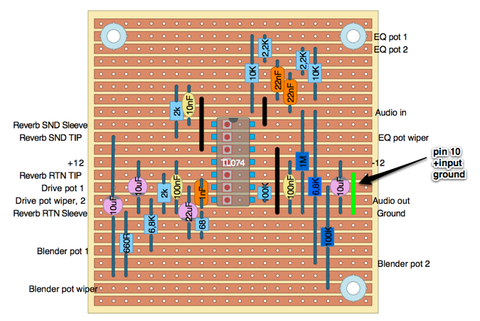
Tombolaspringreverb

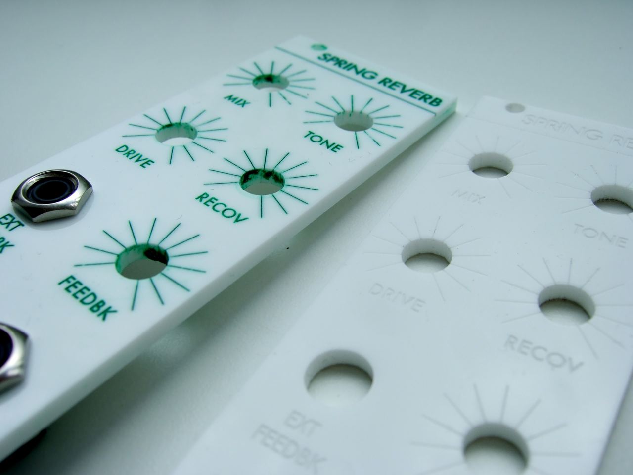
I had some panels for this project in the batch I ordered from Razorlab, this time infilled with emerald green acrylic paint. Makes me want to drink Pimms and eat strawberries and cream. Maximum recommend for Razorlab by the way, although you might have to go via Ponoko to get it done.
Dscf5044

So here’s my version of the module in, erm, 8HP. So I could’ve just bought the Doepfer version then. Anyway. Ta-daaaa.

I added a feedback circuit, with a CGS DC mixer and a switched ext feedback socket – it’s normalled to feed the reverb only signal back into the input, level controlled by the feedback knob. If something is plugged into the ext feedback socket, it mixes that into the input instead. I also added a 1k drive pot instead of the 660R resistor. This helps a lot when switching in different spring tanks via the (handy) phono jacks on the front – most of my motley collection of tanks mostly seem to need a higher drive than the specified 8EB2C1B.

I looked at putting the spring tank connections on a single socket, having missed out on putting an separate output for reverb only, but because the sleeve outputs on the circuit can’t be tied together (they’re not grounded), we’d need a 4-pole socket. Because of the size of the holes in my panel, I tried for one of these.

Img_1070

It turned it out it was nearly impossible to solder wires to the terminals with my clumsily massive iron without melting the plastic dividers. So I gave up and put a stereo jack on the output; one side mix, the other side reverb only.

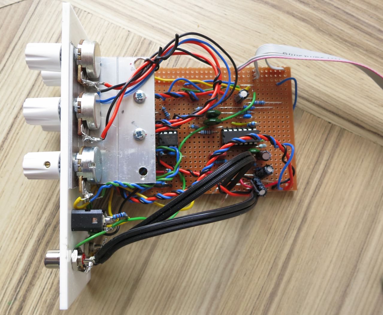
Round the back, oh dear.
Img_1152

…mmmm. Well it works. My home-made shoddy PCB bracket made out of aluminium L-channel looks a bit better with the blood cleaned off it, at least. I’ve run shielded wires between the board and the sockets for the spring reverb tray in an attempt to try and minimise any hum picked up inside the case.

Because of the additional feedback circuit, added at the eleventh hour, it’s pretty deep and just about fits inside my Doepfer LC9 case. I’d usually favour stripboard but I get the impression that pointboard would produce a more compact layout, probably handy if space is tight. Either way if the sound of springs is your thing I recommend not waiting for someone to knock up a PCB, just have a go.

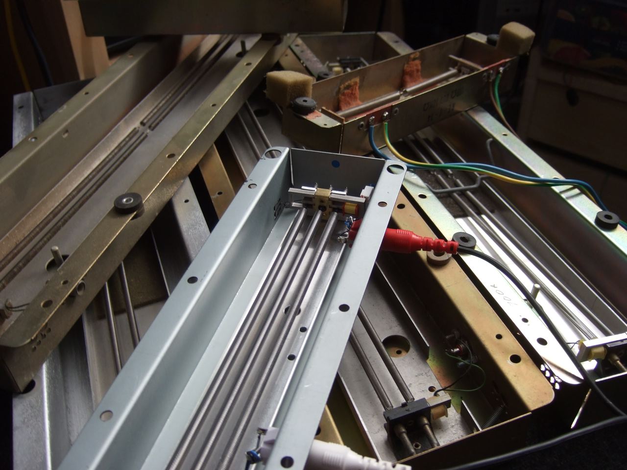
Here’s my pile of springs, mostly ancient trays presumably yanked out of Hammond organs.
Dscf4979

And finally some short demos with the specified 3 spring 8EB2C1B tank, just to give an idea of what it sounds like.

This is an early one, fiddling with an MS20, sequenced from the A-155 through the reverb with the driver circuit running at +/-15v. Murky.

Some more beats, the sound source being Marc Bareille’s Polivoks filter clone with the resonance up, being fed through a couple of CGS30 bandpass filters, including some fiddling with feedback, and pushing the drive.

Another loop from the Polivoks/bandpass filter setup.

This is an 8 step sequence from the A155 into an ASys RS95 oscillator. The distortion is the spring being pushed too hard when turning
up the drive. Again at the end I’m playing the feedback, trying to get it ring without whining.

Update – Oct 2013 : Tom Whitwell has designed a PCB for a new version of his spring reverb; all the information over at Music Thing and the inevitable thread over at Muffwiggler.

tombola's spring reverb circuit

Oct 2017 : The original schematic seems to have gone walkabout from the thread at Muffwiggler – here it is (updated Feb 2019 with correction to capacitors in tilt EQ subcircuit):

135 comments

  1. 8th September 2013Simon Smith says:

    Hi, could you tell me what values for the pots you used? I would love to build this. I only have a small practise amp but I do have a scrounged reverb tank. Thanks

  2. 8th September 2013ua726 says:

    I think I pretty much stuck to the values that Tom specified; 100k for blend/mix, 50k for the drive/recovery, 1k for the extra drive pot I added, and 20k instead of 25k for the EQ/tone pot just because I didn’t have a 25k pot to hand. All linear as far as I can remember.

    I tapped pin 7 of the TL074 for the 100% wet output for the feedback.

  3. 16th June 2014snaper says:

    Hi,

    Could you confirm that the above poste layout works? I mean without any change?

    Thank you in advance!

    Regards,
    Gábor

  4. 16th June 2014ua726 says:

    Hey Gábor

    I built that layout ages ago, and it worked. If you want a PCB then Thonk sell Tom’s latest version of his spring reverb.

    cheers

  5. 29th July 2014trash23 says:

    yes it works! thanks!

    Peter

  6. 29th July 2014ua726 says:

    glad to hear it!

  7. 19th November 2014dr knob says:

    hi, i do not understand what it’s wiper. Maybe connect pins 2 and 3 for poti?

  8. 21st November 2014ua726 says:

    The middle pin of the three.

  9. 23rd November 2014David says:

    Hey, thanks for publishing this. As someone with almost no electronics experience, I managed to get the main circuit together pretty easily.

    I’d like to add the feedback circuit as well, but, like I said, with no electronics experience I have no idea how to do that. Do I need a second TL074? What would the circuit itself look like?

  10. 25th November 2014ua726 says:

    @david Glad you got it working!

    Cleverly I didn’t make a schematic for the additional feedback stuff, but it’s mostly just taking the reverb only out from pin 7 of the TL074, and mixing with the audio input through a CGS DC mixer (http://www.cgs.synth.net/modules/cgs04_mix.html, just a dual op amp – like a TL072 – and a couple of resistors), The output of the TL072 would then be fed into the track marked audio input above.

    The feedback input to the TL072 mixer should go through a pot to attenuate it, I think I used one with an audio taper – it took a bit of experimenting to get something that gave control over the right level of feedback, it can be a bit touchy.

    Dunno if any of that makes any sense, given a bit of time I could work out exactly what I did and do a revised layout if it’ll help, but I’d recommend you have a go on a breadboard in the meantime.

  11. 25th November 2014David says:

    Thanks so much for the reply. I think I mostly understand it; I get how frustrating it can be for newbies to post simple questions, so I’ve got a textbook here that I’m reading to help get me up to speed. Right now I’m waiting on some parts to arrive (I decided to also attempt that Polivoks filter clone you linked to) and once they do I’ll give it a shot. So thanks again!

  12. 26th November 2014ua726 says:

    It’s nice to get comments tbh, makes a change! I’m very bad at asking for help, I tend to stare at something for months, like the System 100 VCO I eventually got sorted.

    The Polivoks is great, but I was just starting off with building things at the time and never quite got the resistor changes perfect for 12v, so a couple of the pots have a zero point at about 7 on the dial, which is mildly annoying but it works ok.

  13. 27th November 2014dr knob says:

    Thanks ua726 it works perfectly!
    There are slight shrill whistle, i hope to disappear by shielding the cables. Excuse me if i make gramatical mistakes, i’m french.

  14. 27th November 2014ua726 says:

    excellent! Moving the spring reverb tray around might help a bit too, I have mine balanced on top of the case.

  15. 7th December 2014David says:

    Hmm okay, so it didn’t actually work. I had it all wired up and assumed everything was okay, but when I plugged it in, SNAP! and smoke. I’m not sure what happened, since I can’t see any shorts and none of the components look damaged. I think I might’ve blown the opamp. I’m going to try again, but I wanted to ask: what do those white circles on your diagram represent? I ignored them the first time since they were unlabelled, but now I’m wondering if I missed something.

  16. 7th December 2014David says:

    Ah, I know what the problem is. In my ignorance I didn’t realize this circuit needed a bipolar power supply (I didn’t know such a thing existed until now). I’m not sure how to adapt my regular 12v power supply to make this circuit work.

  17. 7th December 2014ua726 says:

    Yep, you need a +/-12v power supply. +/-15v should work for this as well, although 12v is the most popular with Eurorack DIYers.

    The cheapest/quickest way of just being able to hear something might be to wire up a pair of 9v batteries in a bipolar fashion (explained http://www.electro-tech-online.com/imgcache/638-osc_27.gif). It might not sound as good though, and that’s not really a permanent solution.

    I made a simple stripboard +/-12v power supply a while back, it’s OK – it was based on the MFOS power supply.

    Since most of the things I’ve been building recently have been designed for 14v or 15v, I’ve moved to using an Oakley PSU which isn’t the cheapest option, but it’s great for testing. Generally if something is shorted, a pair of lights on the board go out and I jump for the off switch. The output voltage is adjustable within a certain range so it may be possible to run it at 12v but I’m not sure – it might be worth asking in the Oakley Muffwiggler forum if it’s possible to modify the design for the lower voltage.

    If you’re in the US then there are generally piles of PowerOne power supplies going cheap on eBay (like this), but being partly open, it seems too easy to electrocute yourself. The Oakley/MFOS/Frequency Central PSUs all use enclosed wall-wart type transformers, which seems a lot safer.

    The white circles on Dego’s diagram must be for mounting holes, but I wouldn’t put them there because you’ll cut the tracks to the EQ pot. I should just check you realise that the red squares down the middle of the TL074 are cuts in the track.

    Before you plug anything else in, I’d check that you aren’t getting any shorts with a continuity tester in a digital voltmeter. I do this now before I plug a newly built module in, checking that the power supply lines aren’t shorted, that the power pins on all ICs are connected to the correct lines, and that adjacent tracks aren’t shorted (unless they should be). In the past I’ve missed shorts with a visual check, only picking them up when checking with the continuity tester.

    phew hth

  18. 8th December 2014David says:

    Thank you so much for the reply. It’s extremely helpful. I guess now I just need to figure out how far I want to take this and in what direction. It’s funny that the two initial projects I’ve chosen require different voltages, so I’m not quite sure where to start. Part of me is thinking that the best idea now would be to just order two PCBs from Frequency Central and build both 12 and 15 volt versions (or maybe an Oakley 15v and an FC 12v). I suppose I should also do some research into modulars to find out where I’ll most likely end up. In the meantime I really do appreciate your help. It’s hard to break into a scene like this, where everyone seems to know so much, but posts like yours certainly help 🙂

  19. 10th December 2014ua726 says:

    If I was just starting out, I’d just probably get a kit 12v Eurorack style power supply. There’s definitely a wider selection of PCBs and projects available at the lower voltage. FWIW, my Polivoks filter is still running happily in my (12v) Doepfer case despite the aforementioned wonkiness.

    Also check out the Muffwiggler DIY and Eurorack forums, the electro-music DIY forum, and the Analogue Heaven and Synth-DIY mailing list archives, it’s all in there, it’s an entire world. There’s a massive list of links here – http://www.sdiy.info/w/Synthesizer_Do_It_Yourself

  20. 28th January 2015David says:

    So it’s been a few months, but I ended up getting a used Power One supply and rigging it up for +/-12v, and it seems to work really well. That let me get back to the reverb circuit, which I rebuilt from scratch, and — holy mother of God — it actually sorta worked! Now that it’s at least partially working, I have some more specific questions.

    The overall level seems to be pretty low. I’m using an Acutronics 4ab3c1b (from a Twin Reverb), so it’s got 8ohm input impedance and 2250 ohm output. Anything I can do to bring the signal up? I’ve been testing it with an MS20 mini, and I can only get usable levels with the headphone out at over half volume with my audio interface preamp at like 3/4.

    Secondly, I haven’t been able to get the feedback circuit working. The feedback pot doesn’t seem to do anything at all. I took pin 7 of the TL074 (after the 1n cap) and sent that to terminal 2 on the feedback pot. Then I took the wiper terminal and sent that to the input of the DC mixer, and I grounded terminal 1 of the feedback pot as per Ken Stone’s schematic. Finally I ran the output of the TL072 (pin 7) into the audio input line on the main circuit, and I put it just after the input jack. If that all sounds good, then I’ll go in with the multimeter and make sure everything’s fine, but I wanted to make sure I had the basic signal path right first.

  21. 28th January 2015ua726 says:

    @david, glad it’s kinda-sorta working at least 🙂

    When you say overall level, do you mean the mix of the original + reverb, or just the reverb?

    The reverb level could probably be tweaked by varying the 660R resistor, try a 1K pot instead. Most of my collection of dodgy old springs can be made to work this way, although watch out for distortion.

    If the overall mix level is low, I imagine you could vary the 100K between pin 8 and 9 of the TL074, maybe make a bit smaller (68k? I haven’t tried it) Have to say that the level on mine is fine running from the send on my Yamaha mixer, with the audio straight back into another channel, gain fairly low.

    Here’s the schematic if that’ll help:

    http://www.muffwiggler.com/forum/userpix/4235_spring_reverb_v3_1.png

    Your feedback plan almost sounds right, here’s a dodgy diagram I just knocked up, you might need to open the image up in a separate window if it’s too small.

    spring reverb feedback

  22. 28th January 2015David says:

    Oh, I see, I need to put the main input through the mixer too. That’s helpful, thanks! I know that i take the feedback from pin 7 of the TL074, but should I take the sound input right from the input jack itself?

    I should’ve been more clear in my original post — it’s the reverb signal that’s weak. The original signal is quite loud and clear. I have the 1k drive pot in place. I’ve been toying with the recovery resistor, and that seems to help. I’ve even tried removing it altogether and just using the drive pot, and have actually gotten some good results that way. You kinda have to work the blend and drive knobs in tandem, but I like that the drive knob can add a touch of reverb even if the mix is 100% dry. It can distort a little more easily, especially when the tone knob is down, which seems to boost the lows a lot, but it’s workable, although not a setup you would ever find on a retail reverb 😉 I’m not running it through any sends, though. Just the MS20 into the verb into one of the line-in channels on my interface.

    After playing around with it all day, it really does sound quite good, just needs a little more adjustment. Thanks again!

  23. 28th January 2015ua726 says:

    Yeah, the thing I’ve labelled “sound input” on the DC mixer just becomes the input for the spring reverb as a whole, the DC mixer becomes the front end for the spring rev driver. It’s a bit cranky, I’ve found that the blend doesn’t always take the reverb completely out like you say, possibly the resistors need to go a bit lower there.

    This article here covers making a spring reverb driver work for different spring impedances

    http://sound.westhost.com/articles/reverb.htm

    …although inevitably the circuit is a bit different, I think that R7 on that circuit roughly corresponds with the R2 in Tombola’s circuit, so it might be worth varying that 2K a bit. Enjoy fiddling, it’s addictive though…

  24. 29th January 2015David says:

    I didn’t quite get the feedback circuit working, but replacing the recovery pot with a 150k fixed resistor makes it work pretty well with my MS20. It actually sounds fantastic now, kinda reminds me of old BBC Radiophonic Workshop stuff, although I’m not sure they had springs back then.

    Anyway, I really appreciate the effort you’ve put into helping me . I definitely wouldn’t have got it together on my own 🙂

  25. 27th April 2015Ed says:

    I’ve just built this and worked first time. I replaced the 660r resistor with a 1K pot and added a feedback circuit. I didn’t think the CGS style mixer stage is really necessary and I just took a line from pin 7 and looped it back to the audio input without any additional opamp buffering via a 47k pot and a 100r in series. That makes it similar to a few guitar pedal feedback mods I have seen. Everything sounds excellent-thanks for a great circuit!

  26. 27th April 2015ua726 says:

    Fantastic, glad to hear it works. I didn’t do nothin’ really, it’s all Tom Whitwell’s circuit and Dego’s layout.

    Agree that the CGS mixer is probably overkill but that’s what I do really 🙂

  27. 8th September 2015Fredrik says:

    Hello.

    I have the driver doepfer a199. I have changed the tank to a long tank with two springs.
    But i feel that i has lost a bit of its power even thug i checked the ohms before i ordered it from tube doctor.

    Now i starting to wonder if i have to build a own driver. Are you driver suitable for my tank do you think?

    My goal is to have the same sound as you can have from the classic grampian 636.
    With that said i mean the snatchy and clatchy sound that you want in dub music.

    Thanks / Fredrik

  28. 8th September 2015Fredrik says:

    is it possible to add a LED for input signal in this schedule?

  29. 9th September 2015ua726 says:

    hello Fredrik

    Heh, I heard someone else’s A199 and thought it sounded great with the small tank.

    I can’t guarantee that your tank will sound any good with Tombola’s driver circuit as standard, but you should be able to vary the drive to get a reverb sound out of it. Like I said, I bought a job lot of old Hammond organ springs, and they all sound a bit different, some better than others.

    As to whether it sounds like the Grampian 636, also no idea! First I’d heard of it, to be honest. I know Tubby used a Fisher Spacexpander, and I always thought Scratch used a Space Echo, but that was just going from pictures. I haven’t tried to play the kind of scratchy instrumentation they would have used through it, all my fiddling has been with farty-sounding analogue synths.

    I would think that either the A199 or this would be good enough as a starting point, along with a tape echo and plenty of eq fiddling.

    As for the input LED indicator, you might be able to adapt Ken Stone’s LED driver.

  30. 27th December 2016Ted K. says:

    Hey thanks so much for this! I’m like beginner-intermediate to electronics but I just found this bipolar supply that seems almost too good to be true in my search for bipolar supplies: http://www.futurlec.com/Mini_Power_Dual_12V.shtml
    It looks to me like it’d totally work and is only 10 bucks, what do you think?

  31. 27th December 2016ua726 says:

    I reckon it’d power the spring reverb circuit mentioned in this post, plus maybe one or two other small-ish circuits – but I don’t really know for sure, ‘cos I’ve never measured how much power the spring reverb circuit draws, and I can’t see any info about how much power the Futurlec PSU could provide.

    The “output power of up to 1A” bit I imagine is about the DC transformer you’d plug into this to power it – I’d imagine the maximum reliable output current from this board would be a lot less.

    The datasheet for the regulators might help give you some idea of how much current it could provide. Doesn’t look like there’s any heatsinking (which would help), and there’s not much room for retrofitting any.

    Futurlec tend to be slow and rubbish at telling you when they’re waiting on stock – I had particular trouble with ordering slide potentiometers from them, despite appearing as “in stock” on their site. You might find similar to this on eBay from other vendors.

    I’ll stick to my big-arse heavyweight linear supplies (Oakley PSU board + Yamaha PA-20) for most stuff – reliable power means one less thing to troubleshoot – but for ten bucks I’d be tempted to give this (or similar) a go for a couple of modules.

    I’ve got a Meanwell switcher around somewhere as sold by Curetronic that I’ve never got round to testing out, they might be worth looking at too – although they’re rather more expensive.

  32. 1st February 2017Ezta says:

    Hi I am about to attempt to build the circuit in the diagram. Have just read the comments and am wondering about power supplies. Will a standard 12v dc work for this? Cheers!

  33. 1st February 2017ua726 says:

    Soz, you need a power supply with a dual output, +/-12V would work.

    For a quick check it might also work with two 9V batteries like this http://www.instructables.com/id/Dual-Voltage-Supply-9V-batteries/ but I haven’t tested it. My DIY 808 bass drum boomed happily when powered from such a set-up.

    If you fancy doing more of this, then buying/building a +/-12V power supply would be a good idea – something like http://store.synthrotek.com/Eurorack_5A_Power_Supply_System_PCB might do the trick.

  34. 2nd February 2017Ezta says:

    Cheers for the response! I will definitely try the battery trick.

    Would any of these do the trick for a more permanent solution: https://www.quasarelectronics.co.uk/Category/kits-modules-dual-polarity-power-supplies

    Sorry I don’t know much at all about power supplies!

    Cheers 🙂

  35. 2nd February 2017ua726 says:

    This one would do the trick

    https://www.quasarelectronics.co.uk/Item/velleman-k8042-symmetric-1a-power-supply-kit

    and assuming you don’t fancy doing some mains wiring (I wouldn’t recommend it) – couple it with a Yamaha PA-20:

    https://www.thomann.de/gb/yamaha_pa_20.htm

    which is centre tapped 17.5V-0-17.5V.

    You might be able to get away with just using a single phase wall-wart type AC adaptor, have a look at the wiring suggested by Tony Allgood for his PSU, you might be able to adapt it.

    http://www.oakleysound.com/rpsu1-um.pdf

  36. 2nd February 2017Ezta says:

    Would this do the trick: https://www.quasarelectronics.co.uk/Item/cebek-fe-21-symmetrical-power-supply-module-12vdc-1a-with-230vac-transformer

  37. 2nd February 2017ua726 says:

    I’d say so, but mains wiring.

    (Years ago I shocked myself trying to fix my CSQ-100, decided it was a lesson learned)

  38. 2nd February 2017Ezta says:

    Thankyou very much for the info. Really appreciate. Will try and build and let you know the outcome

    Ezra

  39. 2nd September 2017Lukie says:

    Need to say the TLE2074 is a huge improvement on this….loads of noise is gone now 🙂

  40. 22nd October 2017Tombola’s DIY spring reverb driver circuit | The Paupers Electronic Music Studio says:

    […] https://ua726.co.uk/2012/07/08/tombolas-diy-spring-reverb-driver-circuit/ […]

  41. 18th February 2018Nick Biederman says:

    I built this on a piece of Veroboard with the intention of using it as a standalone unit for an electric guitar. I’m using a 8EB2C1B tank and a fixed resistor rather than the pot you mentioned as I don’t intend on swapping tanks. I’m powering it using an old Tip Top uZeus PSU I modified by replacing the switch with a jumper so it’s always on and extending the DC power socket so I can mount it in an enclosure more easily. I’m driving it using +-12VDC. For testing, I was initially using a center tap 36VAC transformer with a +-12VDC power supply, but had issues with magnetic coupling of the transformer and tank so I switched to the uZeus. I have not added the feedback circuit. While it works, my dry signal is much hotter than my wet signal even with the drive pot maxed out. Do you have any recommendations on how I could increase the output level of my wet signal so it matches my dry signal? My assumption is that changing the value of R2 to increase the drive of the signal before putting it through the tank or the value of the drive pot to increase the level of the wet signal when it returns from the tank would do it, but this is a more complicated circuit than others I have designed so I’m not sure what the best option would be.

  42. 18th February 2018ua726 says:

    This is where my terrible lack of electronics chops is going to show itself…

    Given that you’re using the same type of tank as I was, and presuming you’re using the full circuit with the blend control, you should get a decent level of reverb out, it might be worth checking your layout first off (soz, I have to put this in). I was running it in my Eurorack at +/-12V and it’s been a while since I’ve connected it all up, but I don’t remember having a problem with the level of the reverb.

    Just done a quick simulation in circuit.jar to check my assumptions, and increasing R2 or decreasing R10 should do the trick – the latter is what I was doing with my extra drive pot. Obviously it might get to a point where you’re overloading the springs, so I imagine increasing the resistance of the recovery/”drive” pot across IC1B should boost the level coming back off the spring.

    Decreasing a resistor is usually a bit easier to test (I think this is why I went for varying R10) – you could clip in a resistor in parallel to do a quick check.

  43. 20th February 2018Nick Biederman says:

    Thank you for your help. I completely understand why your first reaction is to verify the circuit is working correctly, as most of the time the issue is something wired wrong.

    Dropping the value of R10 definitely helped, but I was worried about overloading the springs as you mentioned as I had to drop the resistance significantly (I was down to 340 ohm). In the end, I paralleled a 1k resistor to R10 which drops my resistance to around 400ohm (as I was using a 680 ohm resistor initially) and putting a 25k resistor in series with the drive pot.

    Again, thank you for your help. I just need to get an enclosure built and I’m all set!

  44. 20th February 2018ua726 says:

    Excellent, glad you’ve sorted it

    I just need to get an enclosure built…

    ah, this is the difficult bit 🙂

  45. 8th March 2018Will says:

    Just finished building this on Vero..

    I’m getting a full dry signal through, but nothing reverb-y at all. When I turn the blend knob down I get a very very quiet sound. I’m not getting any action in my spring reverb at all.

    Would this mean a fault in the spring drive or recovery circuits? I guess even my spring tank could be faulty but I thought these were pretty simple indestructible things.

    Have you got any thoughts on this?
    In the meantime I’ll continue to check through for mistakes. Cheers!

  46. 8th March 2018ua726 says:

    Before I run out, some random thoughts to help troubleshoot:

    – Do the boring checking stuff (make sure you’ve got + and – power to the IC, make sure you’ve no solder bridges)
    – see if you can gently probe on pin 1 of the IC for audio output (if there is sound, the drive is at least doing something)
    – is the spring reverb the same type as specified? others may need connecting slightly differently or more drive
    – related, make sure you’ve wired up the spring correctly. check your connector wire (I have a collection of ancient shit phono leads, I don’t trust them)
    – gently(ish) bang the spring, do you get a thunder-y kind of sound? if not, the recovery circuit isn’t working.
    – (from ancient memory) if you turn up the input to the spring and put your ear next to it, you should be able to hear the sound being passed through it.

  47. 8th March 2018Will says:

    Thanks for getting back to me!

    Update: When I twang the springs by hand, I get reverb! So clearly there’s a problem with the driver circuit. I checked the spring reverb by using a headphone amp to power an aux send from my mixer, so it does work, it just needs a lot of gain!

    I’ve been using a 1k pot for R10 but this seems to make no difference on the verb. Could it be that this circuit can’t drive my spring? I’m using Accutronics 4DB2C1D which is 250ohm input impedance.

    I’ll inspect the gain circuit for shorts.

  48. 8th March 2018ua726 says:

    I’d definitely check the input of IC1A (pin 3) and at the outputs to the spring, either by using an oscilloscope or use a makeshift audio probe (like this one here: http://www.diystompboxes.com/wiki/index.php?title=Debugging).

    If you’ve got lots of level coming out of this then I wonder about varying R2, although this circuit has worked with my dodgy collection of springs.

  49. 8th March 2018Will says:

    Cheers for the heads up. Sorry for all the questions!

    I’m playing a drum machine through the circuit, and I’m hearing the full signal regardless of whether I have the power plugged in.. does this suggest a short? Or is some passive signal included in the output.

  50. 8th March 2018ua726 says:

    With the mix control full on the input (and with no power lead connected to the system) I get the input signal on the output, near enough. With mix control all the way over to the spring, I get a faint bleed from the input signal.

  51. 15th March 2018Will says:

    Hi again!

    Thanks for showing me that audio probe, will be really useful for future projects.

    So I tapped IC pin 3 with it, and I’m getting fine signal there.

    When I tap the Reverb Send Tip I do get a signal, but it’s incredibly faint… I also get hardly any signal when I tap pin1 of the IC either…

    Have you got any thoughts on this? Seem’s like the problem lies in that spring drive circuit..

    Will

  52. 15th March 2018Will says:

    Would it matter that I’m using a TL074BCN chip? I don’t know if the pin layouts vary on them, I assumed all 074’s were interchangeable.

  53. 15th March 2018Will says:

    UPDATE:

    I just tried a new power source and blew the IC.

    I think I’ve wired C3 (1nf) wrong. I wired it from pins 5 to 7 as the vero layout was confusing. From the schematic though it should be in parallel with the drive pot. Please could you confirm this?

    Similarly, it shouldn’t matter which way the AC is connected since it has no polarity.. right?

  54. 15th March 2018Will says:

    It seems like the power supply I was using previously was a dud, hence the signal going into the opamp but none coming out (or only very faintly).

    When I changed the power supply to a working one the wrongly situated cap shorted the IC and blew it.

    Hopefully if I replace the TL074 now and with the cap in the right place I’ll have some nice twangy reverb!

    My intention is to make an external box to house the tanks I have, with a switch on the front that can select between the different reverb lengths.

  55. 15th March 2018ua726 says:

    Soz I’ve been away this evening twiddling with my S1000; got an external CD-ROM working with it, so I’ve been loading up all sorts of silly old rave stabs.

    Glad you’ve got it sorted now anyway, congrats!

    To answer your questions anyway, yeah, C3 (the 1nF) is definitely between pin 6 and 7 – the stripboard layout could be a bit clearer there. You can always check on the schematic if you’re not sure.

    TL074s don’t vary in pinout as far as I know, that one should be fine.

    Like I say it’s always worth checking that everything is getting power like you expect. Before I power up a board, I always do a quick continuity check on + and ground, and – and ground to make sure I’m not shorting the rails out.

    Also I’ll power up a board without ICs, and check the IC power pins with a multimeter to make sure they all get power correctly. On first boot with all the ICs in, I try and look at the chips and the power supply (an Oakley), which has LEDs on both rails. If too much current is drawn they go dim (and I know to quickly flip the switch off).

    good luck with the box making! (I can’t help with that bit, sozza)

  56. 23rd March 2018Will says:

    We have lift off!!

    Got the circuit working perfectly, bar some parasitic coil whine originating in the PSU. A massive thank you for keeping up to date on this blog and replying to all my irritating questions. Big props.

    Will upload some piccies when it’s all racked up.

    Will

  57. 24th August 2018David Daigle says:

    I see on the plate you have a potentiometer called “Recov” where is this in the schematic? If it isn’t in this schematic then where should it be? I understand the feedback which is just a summing circuit that sums the reverb output back into the input.

  58. 24th August 2018ua726 says:

    Hello David – from my notes, the “drive” pot on my panel is a replacement for R10 in the schematic, instead using a 1K pot.

    My “recovery” pot is the 50K pot confusingly noted in the schematic as “drive”, but in the “recovery circuit” section.

    You can call them what you like – to be honest, I did 🙂

  59. 30th September 2018Nicolas says:

    Hello! first of all congratulate you on the post and all the help work in the comments. I have built the circuit and it really sounds very good, but I can not get the wet signal isolated, I have read the comments but I can not understand how to do it, can you help me by drawing a small scheme?

    Thanks in advance

  60. 3rd October 2018ua726 says:

    Sorry Nicolas, I’d only just seen your comment.

    Try pin 7 from the TL074, the output from IC1B in the schematic at the bottom of the post for the wet signal.

  61. 17th November 2018Will says:

    Back again! The verb works great, I’ve got it racked up in a little DIY 19” box. Is there anyway I can send you a picture?

    Also, the level of output seems quite low on mine. I’m using it as an aux send on my mixing desk and I can’t seem to bring the return level up loud enough unless I boost it hard into the spring and it distorts.

    I’m thinking of sticking an Boss pedal compressor after the output to boost it more cleanly. Does your own unit have enough output gain?

  62. 18th November 2018ua726 says:

    Hello Will – maybe bung a photo on imgur or something and include a link in a comment?

    As far as I can remember I’ve only ever used mine in the context of my modular synth where I expect the signal levels will be a lot higher than an aux send on a mixer, and it’s always been plenty loud enough.

    Is it the total signal (dry+wet) or is it just the wet signal that’s quiet? If it’s the total mixed signal, I’d suspect something up with the blend pot or the inverting buffer. If it’s just the wet signal, did you implement the pot on R10 to vary the drive going into the spring?

  63. 25th February 2019brnd says:

    Hey there! Just built this on a pcb. Great so far!

    Am just having one problem, if i turn the ‘drive’ pot in the recovery section up, even a little, i’m getting feedback in the spring reverb. Anything i can do about that ?

  64. 25th February 2019ua726 says:

    Mine isn’t connected up at the moment, but this doesn’t sound familiar. I’ll see if I can get a chance to wire it back up tomorrow and check the behaviour of mine.

    I guess it’s possible that the audio in the room might be having an effect but I’d guess you’d have to be listening at near-deafening levels for that to be a factor, so it seems unlikely.

    Wonder if it’s something to do with the tank, what sort are you using?

  65. 26th February 2019brnd says:

    Hmm, no definitely not deafening levels. It also occurs when the speakers are off. The tank is a standard one I got from an old guitar amp.

    I’m going to check everything once more and do some troubleshooting. Thanks for the help !

  66. 26th February 2019ua726 says:

    Just to say I’ve hooked up my Eurorack modular again and tried three different spring tanks – a short modern three-spring Belton 8AB2D1A, a short two-spring tank marked “in 8 ohms, out 10kohms – RE-4-14”, and a 12 inch long two-spring tank with no markings on it at all, and they all behave themselves when yanking on the drive pot in the recovery section.

    Did you incorporate a feedback pot in your version?

  67. 27th February 2019brnd says:

    aah, there was a problem with my wiring of the in and out jacks. something with the switches in there. it works like a charm now !

    i didnt use the feedback circuit for now. i am going to use the 1k ‘drive’ pot instead of the 660r which seems like a nice touch.

    i think i’d like to have the tone control be a bit more aggressive (more cut when turned left and more high boost when turned right), do you know if that could be easily accomplished by changing the resistor values or capacitors? thanks 🙂

  68. 28th February 2019ua726 says:

    @brnd – excellent, glad it’s working!

    On the tone control front, you might want to check that you used 22nF for C1 and C2 rather than the 0.22uF / 220nF capacitors mentioned in the schematic – I’ve updated the drawing.

    Presuming you have used 22nF caps and you still want to make it more aggressive… er, dunno. Have a search on Google Books for the “ambler tone circuit”, it should lead you to Douglas Self’s Small Signal Audio Design which is where the original designer of this spring reverb driver got the circuit from.

    If I want stronger filtering I’ve got a couple of CGS30 bandpass filters next to the reverb, they’re a simple enough build.

  69. 27th February 2019Luke says:

    Can I get some clarification on which capacitors to use? The values on the strip board diagram are 22nf but seem to be 0.22uf in the forum diagram. These are an order different and I’m wondering which is to be used? I haven’t fully checked the circuit, but I think there may have been other discrepancies.

  70. 27th February 2019ua726 says:

    @luke – should be 0.022uF / 22nF, yep – good spot. I’ll update the schematic.

  71. 20th March 2019Luke says:

    Do the dark/light blue resistors indicate anything? Wasn’t sure if this was meaning a difference between carbon film vs metal oxide or not.

  72. 20th March 2019ua726 says:

    Nope, there’s nothing indicated on the schematic – I just used whatever I had.

  73. 21st March 2019Luke says:

    Hello, I’ve prototyped the circuit meticulously on protoboard with jumper wires and everything attached. I’m getting only the dry signal through (with no reverb). Do you have any advice on what should be checked? I followed the stripboard diagram from above.

  74. 21st March 2019ua726 says:

    Sorry if I’m repeating myself, I can’t remember what I said before but I would usually look at the schematic, and use that to follow the signal through on the board, testing with an oscilloscope (or alternatively a really cheap pair of headphones) to see where it stops being passed through. It’s a shame the circuit layout doesn’t have the part numbers on it, makes it a bit trickier, but you should be able to work it out.

    For example check pin 3 of the TL074 to make sure that the signal is making it to the drive opamp, check the input on the spring reverb, check pin 5 to see if the signal is making it back from the spring reverb, then pin 7 to see if there’s an output from the recovery amp.

  75. 24th March 2019Luke says:

    It seems that audio going into the spring is quite loud (loud enough I’m not sure). Audio coming out of the spring is quite quiet (I used a duel spring tank with the same in/out resistance). Removing the 1k recovery resistor and using a direct with connection seems to make the wet signal louder, but it’s still quite quiet compared to the dry signal even when I adjust the mixer to fully favor the wet signal. What should I do to tweak the strength of the recovery circuit or the drive circuit? Can confirm that I hear very quiet sounds on the master output coming from the spring when I smack it a bit.

  76. 25th March 2019ua726 says:

    Should hear quite a thunder when you smack it. Is it definitely connected the right way round? (on some of my old spring tanks, it’s not totally clear which is the input and which is the output). Is it definitely the specified tank? Could try increasing the resistance of the 50K “drive” pot, or putting another resistor in series with it. Is the output loud at pin 7? Are you definitely using the same resistors at R12 and R11 (the two 6.8Ks?) Might be worth just testing continuity through the recovery circuit side.

  77. 30th May 2019ZZ.Clop says:

    Hey there !

    Making this right now and I was wondering if the grey area on the polarized capacitors was indications for the positive legs ? If not, Is there any way for a beginner like me to know which way to connect them ?

    Thaaanks and great job by the way , really appreciated !

  78. 30th May 2019ua726 says:

    Sorry, yeah now you mention it, it’s not obvious. The grey area denotes the negative end of the polarised capacitor.

  79. 30th May 2019ZZ.Clop says:

    Thanks for the quick reply !

  80. 2nd July 2019Jarrod says:

    Hi there!

    Just finished the build but haven’t had much success getting signal through the actual reverb tank. The tank itself is from a Hughes & Kettner guitar amp and seems to work fine when I plug the output straight into a DAW and drive it really hard. I also tried sending audio straight through the tank into the return of the board and that worked, but the signal was still very faint. The circuit is definitely receiving +-12V because I used a multimeter to test it, although pins 2 & 5 (which are the send and return of the spring) are reading as 0.6V or less…which means no signal is going to the reverb tank? All other components in the signal path of pins 2 & 5 also only get around 0.6V.
    I’ve also got a fixed 1K resistor in place of the 660R and 2.2K rather than 2K cus that’s what I could find. Would really appreciate some feedback!

  81. 2nd July 2019Jarrod says:

    Update: I got it working! Realised I had the drive pot on the right side of the board instead of the left, so it wasn’t getting the right signal from the TL074.

  82. 2nd July 2019ua726 says:

    This is the first chance I’ve had to reply today, glad you got it going!

  83. 3rd July 2019Jarrod says:

    No worries, cheers anyway! Time to build a case ;p

  84. 30th August 2019Fabian says:

    Hi. Thanks for a great sounding reverb (according to your samples).
    I seem to have a problem with a very heavy distortion while running signal through the springs. The clean signal with blend knob turned all the way to 0 is super clean but when I blend in the spring and turn up the drive (just a tiny bit) it get heavy distortion and I can’t either hear any reverb/spring-effect. Any suggestion?

  85. 31st August 2019ua726 says:

    All the usual things really, look at the schematic and measure the signal along the way to see if there’s something there.

    It sounds like the clean path (junction of R1/C1 to R12 and then through IC1C) is ok, so it’s something in the drive or recovery circuit. As a start, check that the signal is actually getting to the spring, and then check that there’s something coming back from the spring.

    If there really is no reverb effect, check your wiring, and use a multimeter to check your soldering for bridges between tracks, it sounds as if you might have the clean signal going straight into the recovery circuit.

  86. 1st September 2019Fabian says:

    Thanks for your reply. I’ve triple checked the schematics and there are no bridges. I’ve made an own strip board design based on the schematic shown up here on your page. I guess there must be something wrong with how I’ve made the design of the strip board. I can see that your stripboard design differs from the schematics with some capacitors from +12v and -12v.

    Anyway, I get signal through my springs and it sounds very good when I wobble the springs. The signal disappears when I disconnect the spring. And as I wrote earlier, my input signal gets very distorted trough the springs without getting any “spring-effect”.
    I’ve replaced the 660R with 1K pot. I guess I’ll just have to stick to your strip board layout to work it out.

  87. 8th September 2019moritz says:

    just built this today and it works like a charm – just wanted to say thanks!

  88. 8th September 2019ua726 says:

    woohoo! excellent, glad to hear – enjoy!

  89. 27th September 2019moritz says:

    any idea for adding a cv input to control the blend? i guess a vactrol would work, but i wonder if there‘s a more „proper“ solution..

  90. 27th September 2019ua726 says:

    I haven’t tried this, soz. I think the “proper” way would involve a VCA (or two), and you know that’s going to be a faff, pretty much a module in its own right.

  91. 21st February 2020yomgaille says:

    Hi, thanks for the article, but compared to the schematic, the stripboard has 4 more capacitors: 2 between +12V and GND, 2 between -12V and GND, which one is right, schematic or strpiboard?
    Also, my tank has an impedance of 600, I guess it’s in the correct range compared to the required 800, but if needed should I adjust a component?
    Thanks

  92. 21st February 2020ua726 says:

    They’re an offering to the gods in the form of power decoupling capacitors – the person that made the stripboard layout must’ve added them. Personally I’d keep them, but I imagine you could get away without them.

    On the impedance front, all I can say is that you might want to vary the 660R resistor at R10 on the schematic – I swapped this out with a 1K pot and managed to get every dodgy old spring that I tried to work.

  93. 22nd February 2020yomgaille says:

    Thank you so much for your quick and precise reply, I’ll keep you posted when it’s done 🙂

  94. 12th March 2020yomgaille says:

    Done and sounding great!

    I used a 1K trimmer instead of R10, set around 500 after testing, this is the 3rd circuit I’m making for this tank and this is finally IT, plenty of power to drive any signal into the springs, the tone setting is super useful and there’s no humming or hissing even though I have stuffed everything together in a tight case…

    Thanks a lot!

  95. 12th March 2020ua726 says:

    Excellent, glad to hear you got it running! Make lots of horrible/nice noise with it! 🙂

  96. 11th June 2020Atu says:

    Hi, thank you for sharing this !

    I tried to build it based on this schematic I made but it doesn’t work.
    I get a LOT of noise and I can hear the dry signal (behind all the noise) when the mix pot is set to the max.

    Could you have a look at the schematic I made and maybe point me to the right direction ?

    https://i.imgur.com/29FkIBE.png

    Thank you very much !

  97. 12th June 2020ua726 says:

    Hello Atu

    Sorry, your schematic is really hard to read, and it’s not helped that you seem to renumbered the parts?

    If I trying to copy a circuit diagram I try and make it look like the original, if nothing else it makes it easier to spot mistakes. You’d be better off using separate opamp symbols rather than the symbol of one chip, it makes it hard to see what’s going on. Also the standard is to start off with the input on the left and work towards the output on the right.

    It looks like there’s something weird going on around pin 5 of the TL074 – it looks like it just connects to the reverb return tip, it should also connect to a 2K resistor. There might be more errors but it’d take me a while to work it all out.

    If your circuit layout software doesn’t allow you to use separate opamp symbols or generally makes it hard to layout diagrams in the way I’ve suggested, then I’d use something else. Kicad is a bit wonky in other ways but it’s flexible, and it’s got a lot better over the years.

  98. 12th June 2020Atu says:

    Thank you very much for your answer.

    Indeed, my diagram is not really nice to read, it was the second diagram I made in my life, I learned quite a bit since.

    I’ll try to redo it with the same potential mistakes.

    Also, I don’t know if you are up to it but if you could share your schematics sources that would be awesome but I understand if you don’t want to !

  99. 12th June 2020Atu says:

    Also, are you recommending to use this diagram ?

    https://ua726.co.uk/wp-content/uploads/2012/07/schematic-2019-02-27.png

    (sorry my last message is showing my real name, thx to chrome autocomplete)

  100. 13th June 2020ua726 says:

    The schematic you’ve linked to (and the modified stripboard layout) is all I’ve got, and is the one to use – I don’t have any source files because I didn’t create them.

    Be aware that C4 and C6 are electrolytic capacitors. The stripboard layout in the post shows that the negative side of the capacitor faces away from the opamp in each case.

    It might be worth starting off by making a copy of your schematic, and then renaming the components on your copy in line with the ones on the original – that way it’d be easier to work out which part should connect to which.

    If it helps at all, I’m still making errors years into fiddling with this stuff. Had a problem with another board the other day, wondered why one potentiometer was controlling two things, found that a couple of standing resistors were touching each other at the end, and another had snapped off. Easy once you know where to look 🙂

  101. 14th June 2020Atu says:

    I tried to redo my first diagram but I actually find too many errors so I started from scratch and it’s way more readable now, it will be easier to debug if something is not working.

    Thank you for the info about the caps, I was going to have some issues as I misread C4 and was going to use a 22nF ceramic cap instead 😀

    Could you have a quick look at this new diagram before I order the PCB please ?
    If I can avoid throwing away an other batch, that would be nice 🙂

    https://i.imgur.com/5jSnRVI.png

  102. 16th June 2020ua726 says:

    It looks ok to me, but don’t take my word for it – I’ve just had a quick look.

    Make sure you go over it carefully. (Or build the stripboard layout!) Also check the polarity of electrolytics against the stripboard version – for some reason it’s not marked on the schematic.

  103. 20th June 2020Atu says:

    I’m completely lost, I made the module on breadboard and it was not working so I made the stripboard version as shown in this post and it is still not working…

    When I turn the blend pot to the max, the volume gets really low and there is no reverb whatsoever.

    When I play with the drive button I hear no change.

    Do you have any idea what I could be doing wrong ?

    The reverb tank I’m using is this one : https://www.thomann.de/be/intellijel_designs_springray_medium_tank.htm

  104. 20th June 2020Atu says:

    Ok, sorry for spamming your comments, the module is actually working, the cable I was using was faulty -____-‘
    Thank you very much for your time and quick responses !

  105. 20th June 2020ua726 says:

    Whoop, glad you got it working!

    I’m certain that everything I’ve made I’ve had the same problem, even the daft thing I’m working on at the moment. It’s always a good idea to follow the signal path through the circuit, and see where it disappears, and then suspect the thing before it.

    I probably mentioned this elsewhere in the comments but if the signal is getting to the spring reverb, if you listen to it in a quiet room with the input level into it jacked up, you should hear the springs vibrating. To test if the signal is being returned from the spring you can (gently) bang the reverb and it should make a thundery sproooing sort-of sound.

    enjoy your new reverb!

  106. 22nd February 2021dazziep says:

    just wanna double-check, the 10uf and 22uf are electrolytics yeah?? but the polarity isn’t on the schematic??

    I know it works using electrolytics as I have breadboarded it and it sounds amazing. the only bit that doesn’t seem quite right to me is the drive (gain) I have to have it really low for my guitar otherwise I just get a LOT of feedback. Then again I did use a 10uf there rather than the 22uf specified (I couldn’t find one whilst breadboarding, I will use 22uf when I solder it up though 😉 )

  107. 22nd February 2021ua726 says:

    Electrolytics, yep – you should be able to get a hint for the polarity off the stripboard layout, there’s a tiny tiny tiny grey bit towards one end of the electro – that’s the minus side. It’s subtle, yep 🙂

    Maybe consider using a smaller pot for the drive if that’s what suits your application.

    I feel that on just using what you’ve got around the place – it’s definitely nice to get things up and running quickly, it’s satisfying.

  108. 22nd February 2021dazziep says:

    WOW super quick response awesome cheers.. yeah I’ll find a 22uf first see if that sorts out the feedback, failing that like you say a smaller pot..
    Thanks for the response mate you are a star 😉

  109. 22nd February 2021ZLT says:

    Hi! Just built one, simple and slick 🙂 Thanks a tone! I’m using Belton 3 sprigs, which have 800 input but only 600 ohm output. Any idea how to increase it? Also this Belton is decribed as input/output grounded, should I ground the sleeves then (instead of verobaord sleeve connection?). Thank you! Best, ZLT

  110. 22nd February 2021ua726 says:

    God bless you all writing in thinking I know how this sucker works. The bible here is probably https://sound-au.com/articles/reverb.htm – table 3 there suggests that the lower the output impedance, the lower the output level, and later on it’s stated

    Reverb recovery amplifiers are fairly straightforward, but the impedance and sensitivity of the output transducer should be chosen based on response and noise. The ‘B’ output coil (in this case 2250ohm) is probably the best of them, as it combines a reasonable impedance and output level, both of which are well suited to most low noise opamps. The high impedance coil does provide more level, but it’s also more sensitive to load impedance and may suffer from high frequency attenuation. The low impedance coil doesn’t have enough level, and will be more sensitive to radiated magnetic fields because of the extra gain required.

    All of which suggests you might want to increase the pot size in the feedback loop of IC1B to boost the output level, and perhaps bumping up the gain into the spring by varying R10, although watch out for overload.

    Like you say, this circuit is intended for a input insulated, output grounded spring, not entirely sure you’d do with a input grounded/output ground spring. Try attaching ground to the sleeve of the spring input rather than the output of IC1A – what happens then? Or does it just work as it is?

    Hours of fun.

  111. 24th February 2021ZLT says:

    Hi! Thanks a lot for a prompt reply. Diggin’ into docs rather says that I need a higher imp output in the spring, so I probably replace it. Anyway, tried grounding output sleeve and it works, but the output level is rather low. R10 swapped for the 1K and is driving the spring nicely. I’ll try with a 100K for Drive then in IC1B. I’d like to add a feedback loop as well and from the above comments and idea with 47K pot with 100R in series sounds reasonably (IC pin 7 to pin2 pot, pot wiper to audio out, pot pin1 grounded). Should it be an audio tapper pot as I assume? Thanks again, you’re rockin’ man!

  112. 24th February 2021ua726 says:

    Honestly can’t remember what I used – I wonder now whether a reverse audio taper pot might be better, like it’d be easier to control around the feedback point. Maybe worth experimenting.

    Also pot wiper would go to the audio in, rather than the out.

  113. 26th March 2021James says:

    Those 4 capacitors (3x 10uF and 1x 22uF) are they polarised electrolytics?

    Thanks.

  114. 26th March 2021ua726 says:

    The purple-ish round things? Yeah. The grey bit on each denotes the negative end.

  115. 31st March 2021James says:

    Have you run this circuit with a tank similar to a 9AB3C1B?

    Long Decay, 3-Spring; Input: 10 Ω, Output: 2,575 Ω, input insulated/output grounded

    I’m not getting much out this on the breadboard.

    Sound input comes from a VCA. Jangling the springs produces nothing noticeable on the scope. Can I get a response in the recovery circuit when jangling the springs and nothing is connected to the input as a way of testing the recovery circuit?

    Thanks.

  116. 31st March 2021ua726 says:

    When you say you’re not getting much out, I guess you mean you’re not getting any reverb output?

    Yep, you should be able to jangle the springs and hear a crashy thunder through the output with nothing connected to the input. Also (given a quiet room) if the drive side is working, you should be able to put your ear to the spring and hear it vibrate with the sound.

    I’d recommend following the path of the signal with your scope to see where the sound disappears, checking your connections, usual stuff. I reckon you should get something out of it as it is, it might just be fairly quiet.

    My dodgy collection of tanks weren’t marked with the impedance, so I couldn’t tell you what I tried. David in the comments here ran it with a 4AB3C1B, which looks like it’d be similar enough, his comments might be helpful.

  117. 31st March 2021James says:

    1k instead of the required 100k on pins 8 and 9. Oaf!

    Thanks for the circuit.

  118. 31st March 2021ua726 says:

    Haha, everyone’s done that 🙂 Glad you sorted it.

  119. 21st June 2021Oli says:

    Hi

    I’ve got the main part of the circuit working no problem and all sounds good, but the feedback circuit doesn’t really have much effect. I have tapped pin 7 and connected it to the wiper of a 50k pot and put a 100r resistor in series the signal is returned from pin 3 of the pot to the track labeled audio input.
    There isn’t much to go wrong here but the feedback pot doesn’t have any effect, well not until its fully open. Then the reverb disappears and I am just left with a distorted version of the original signal. Any ideas what I’ve done wrong?

    Thanks

  120. 23rd June 2021ua726 says:

    Dunno, ‘cos I didn’t set up mine quite like that, I had a probably unnecessary extra opamp stage for mixing the two.

    Maybe try going from pin 7 to one side of a pot, with the signal out going from the wiper to the audio input, and the other side of the pot to ground? The taper of the pot might help somewhat, I’d always thought that a reverse audio pot would be best but ymmv.

  121. 29th December 2021Alda says:

    It is work for guitar? Thanks

  122. 29th December 2021ua726 says:

    Haven’t tried it on guitar, I can’t see why not?

    One thing to bear in mind though; you might be used to pedals that run off one 9V battery – this is designed for a split +12V/-12V power supply, although I imagine it might also work off +9V/-9V from a pair of PP9 batteries wired up in the right way. Or a +18V (or +24V) DC adaptor wired up with a virtual ground. You’d be on your own there, though.

  123. 30th December 2021Alda says:

    Thanks mate, your explaination is very good! I will try

  124. 15th February 2022Zola says:

    That’s great! I’d love to try it with the guitar 🙂 I have a couple doubts though

    What does the recovery 50k pot? Is it like a decay/dwell?

    I don’t understand the feedback thing. I mean, when there’s nothing plugged in to the feedback jack, what happens? Does the pot do something? Also, where do you connect the hot signal coming from the feedback jack?

    As you can see I’m a bit confused about the feedback thing :S

    Cheers!

  125. 15th February 2022ua726 says:

    What does the recovery 50k pot? Is it like a decay/dwell?

    As far as I can remember having not laid hands on mine for a couple of years, on my version it boosts the level coming back from the reverb. It’s slightly confusing on mine in that the recovery pot on my panel is labelled “drive” on the schematic. (I’ve probably mentioned this about 30 times in the comments above, I’ve forgotten now).

    I don’t understand the feedback thing. I mean, when there’s nothing plugged in to the feedback jack, what happens? Does the pot do something? Also, where do you connect the hot signal coming from the feedback jack?

    Might want to consider if you can be arsed with the feedback if you’re going to be using it with guitar, it’s extra complexity and I’d associate it with an experimental modular synth set-up more, but feel free to prove me wrong 🙂

    I explain this in the original post, but I’m using a switched jack socket for the feedback input. With nothing in the socket, the wet only reverb is internally passed through the feedback potentiometer (so I can vary the level) back into the reverb input.

    When there’s a jack in the socket, the pointy bit of the jack will actually push the metal connections apart inside the socket so it disconnects the internal wet only reverb from the input, and instead whatever comes in from the external cable goes through the feedback pot back into the reverb input.

    By going “through the feedback pot” I mean the hot end of the feedback jack socket goes into one side of the pot, with the other side attached to ground, and the wiper/middle pin going back to the input of the reverb. I added a small mixer stage (nicked off https://www.elby-designs.com/webtek/cgs/cgs04/cgs04_mix.html) before the reverb input to mix the feedback input and the original input, but there’s a comment up above saying I didn’t really need that, which seems entirely likely.

    hth

  126. 16th February 2022Zola says:

    Ey, thank you very much!

    I see. So your recovery pot helps you to get the right amount of wet signal into the blend pot. I guess that makes sense if, for example, the blend pot fully clockwise doesn’t give you 100% wet signal. Is that right? If so, I think this pot would be better as a trimmer soldered to the board.

    Yeah, the external feedback jack doesn’t suit guitar set up too much. But I still don’t know if I’m getting the feedback feature right. When fully counter clockwise, that would be as if there’s no pot whatsoever. Then, as you turn it clockwise, it goes from subtle to crazy stuff. Like the feedback control in a delay. Did I get it?

    I’ve read the whole post a couple times before asking. I’m kind of new dealing with reverbs so a couple basic stuff still don’t look obvious to me 🙂

    I really appreciate your help 😉

  127. 16th February 2022ua726 says:

    Yep, you’ve got it right on the feedback front.

    Personally I’d keep the recovery pot but you might have limited space on the front of whatever enclosure you’re planning. Worth experimenting before you put it all together.

    Keep in mind that you’ll need a split power supply (+12V/-12V). You might be able to use a pair of 9V batteries arranged to give +9V/-9V, and that might work to some extent, but I don’t know how long the batteries would last.

    Obviously I’m coming from the angle of using it for synths, if you get it up and running and working well on a guitar it’d be good to see it written up 🙂

  128. 16th February 2022Churro Lightyear says:

    Hey I love this circuit and was wondering if this can drive the 8EB3C1B

    Its literally the same as the 8EB2C1B except its the long reverb version. I don’t know if there’d be any big differences with the amplification to tweak as Ive never touched a spring reverb lmao

  129. 16th February 2022ua726 says:

    I think the 8EB3C1B would be fine, especially if you add a drive potentiometer (replacing the 660R with a 1K pot).

    It’s been a long time since I’ve used this module ‘cos it’s been on loan for a while, but I’ve got something usable out of all of my strange mixture of old spring tanks with this circuit.

  130. 16th February 2022Zola says:

    Great. In that case I think the feedback pot it’s a must. In doesn’t hurt anyone. At least at minimum!

    The dual supply it’s quite easy using a TL054. Its oscillator is in the 30khz range or so. I didn’t make noise whatsoever in other buildings before, but it’s a thing to keep in mind. A CR filter after it would be ideal.

    Ok. I’ll put the recovery as a pot and the drive (1k driving the tank) as trimmer inside).

    I’ll let you know how this end up 🙂

  131. 27th March 2022Zola says:

    I’m back. I works pretty well on guitar with the same tank as yours. Here my thoughts:

    I highly recommend a 50k pot for the EQ (or even 100k). The 25k is too subtle. Higher values will make the EQ much more noticiable.

    The feedback pot is pretty much useless for me.

    A 100k VOL pot instead of the 100k resistor coming from blend wiper is a good idea.

    Ah! For those out there, keep in mind that the mix pot goes from 100% dry to 100% wet. Not very useful for guitar players…

    Cheers!

  132. 28th September 2022deruyterb says:

    A friend gave me his reverb tank from his Fender Vaporizer and asked me to make a guitar pedal from it. I copied this circuit and made the same modifications as described in the article and the comments. I haven’t had the chance to breadboard this yet because I don’t have all the components to test this.

    My main question is: Would this work with a ±9V power supply (made with 1044/7660 type chips) instead of the ±12V?

    I also put a coupling cap C11 between the mixer circuit and the reverb circuit that I’m not sure is necessary, but I guess wouldn’t hurt?

    Link to the EAGLE schematic and board layout (apologies for the EU symbols): https://drive.google.com/drive/folders/17fbXkSvTxJD_Ns2GXOCLRo9unpHRB6ZE?usp=sharing

  133. 30th September 2022ua726 says:

    I think you’ll get some reverb on a ±9V supply, it just might not quite be the same as on ±12V. You’ve got less headroom, that might have an effect, but I don’t know for sure. The feedback arrangement looks fine, although I’ve not had a chance to check the rest of the circuit.

    Can’t give any opinion on your suggested power supply solution – mine is running off a ye olde linear power supply in a Doepfer box.

    Dunno on the 1uF coupling cap front, you could always link it out if there’s no DC offset at that point.

  134. 3rd October 2022deruyterb says:

    Thanks, I’ll just have to wait on some components en start testing. It will take some time but I’ll try to update to maybe help the next person and pay it forward a bit.

  135. 23rd November 2022Daniel says:

    The good thing of creating your own pedals is that you can make them look like you want

Write a comment: